A spring cable for charging pile of new energy electric boat

A technology for spring cables and electric boats, applied in the direction of power cables, insulated cables, and extendable conductor cables, etc., can solve problems such as loss of spring steel wires, displacement of connecting parts, separation of spring steel wires and cable cores, and achieve easy manufacturing and use , improve the service life, the effect of simple structure

Active Publication Date: 2017-11-24
安徽明亮面业股份有限公司
View PDF8 Cites 0 Cited by
  • Summary
  • Abstract
  • Description
  • Claims
  • Application Information

AI Technical Summary

Problems solved by technology

The spring steel wire produced by this process is attached to the inner side of the cable, although the contact with the insulator is reduced, but for the connection between the spring steel wire and the cable, due to the different elastic modulus of the material of the spring steel wire and the cable connection, in the long-term bending and During the stretching process, the fatigue difference between the steel wire and the connecting body will still easily occur, causing the relative displacement of the connecting part to cause fracture, resulting in the separation of the spring steel wire and the cable core, and the loss of the function of the spring steel wire
[0005] In order to solve the problem that the mechanical stress generated by the cable can be evenly distributed on the cable during the contraction and stretching process, instead of applying the mechanical stress to the local point of the cable, the Chinese patent document CN101807779 discloses "A Cable Tray". The traveling distance of the cable is evenly distributed in the hanging wire device, and the connecting spring is added to each wire device. The purpose is to use the stretching ability of the spring to evenly distribute the mechanical stress and prolong the service life of the cable. However, this method is only suitable for horizontal installations. Back-and-forth movement, that is, it is only suitable for vertical and horizontal back-and-forth movement and rotating equipment, such as mobile equipment or lighting power and control lines for film and television stages, audio-visual education, gymnasiums, etc., but for movements with slopes or vertical directions, especially for electric None of the boat charging cables are suitable

Method used


Image

  • A spring cable for charging pile of new energy electric boat
  • A spring cable for charging pile of new energy electric boat
  • A spring cable for charging pile of new energy electric boat

Examples


Embodiment

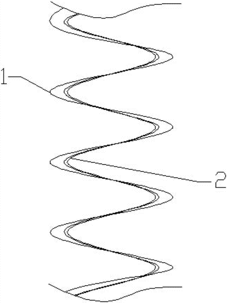
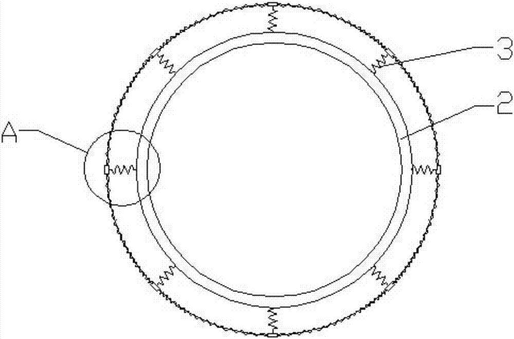
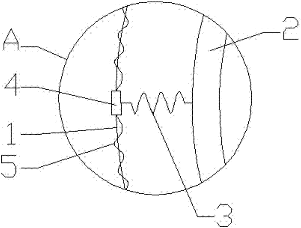
[0025] refer to Figure 1-4 , a spring cable for a new energy electric boat charging pile, including a cable 2, a spring 1 and a connector, the cable 2 is arranged in the inner circle of the spring 1, and the two are connected by a plurality of equally spaced connections The connector realizes sliding connection, the connector includes spring two 3 and sliding sleeve 4, the sliding sleeve 4 is sleeve-shaped, and spring one 1 passes through the inner circular hole of the sleeve-shaped sliding sleeve 4, and the outer surface of the sliding sleeve 4 is also A spring two 3 is fixed; the cable 2 includes a sheath 22 and a plurality of steel strips 23 equidistantly sheathed on the sheath 22, and the other free end of the spring two 3 is fixedly connected to the steel strip 23 , the connecting points of both ends of the cable 2 and the spring one 1 are the same.

[0026] It should be noted that a spring three 5 is also connected between the adjacent connectors, and the spring one 1 ...


PUM


Abstract

The present invention discloses a spring cable for a new energy electric ship charging pile, which includes a cable, a spring 1, and connectors. The cable is arranged in an inner circle of the spring 1, and sliding connection of the cable and the spring 1 are realized by the multiple connectors which are arranged at equal intervals. The connectors include springs 2 and sliding sleeves. The sliding sleeves are of bushing shape, and the spring 1 passes through inner circle holes of the bushing shaped sliding sleeves. The springs 2 are also fixed on the outer surfaces of the sliding sleeves. The cable includes a sheath and a plurality of steel bands sleeving the sheath at equal intervals. The other free ends of the springs 2 are fixedly connected with the steel bands. Connection points of both ends of the cable and the spring 1 are identical. The spring cable for the new energy electric ship charging pile has the telescopic function of the cable and realizes the connection of the spring cable in any direction without any dependence.

Description

technical field [0001] The invention belongs to the technical field of cables, and in particular relates to a spring cable for charging piles of new energy electric boats. Background technique [0002] The electric marine spring cable needs to be frequently moved between the ship and the shore-based charging pile. When the ship is fully charged and puts away the power cord, the cable needs to be stored. When the ship is far away from the charging pile power supply, the cable needs to be stretched out. . In this process, the cable is not only subjected to the pulling or pushing force of the traction, but also the bending stress of the cable and the torsional stress along the axis of the cable. Ordinary spring cables will be wound in random directions during the contraction process, and sometimes the cables will be entangled together, causing the phenomenon that the bending radius of the local point is too small. Due to the frequent crossing of the bending stress and torsiona...

Claims


Application Information

Patent Timeline
Patent Type & Authority Patents(China)
IPC IPC(8): H01B7/06H01B7/18H01B7/22H01B9/00
CPCH01B7/065H01B7/18H01B7/225H01B9/00
Inventor 孙薛燕
Owner 安徽明亮面业股份有限公司
Why Eureka
Try Eureka