
Easy-to-adjust and easy-to-measure high-precision closed constant pressure static pressure guide rail restrictor

The technology of static pressure guide rail and restrictor is applied in the field of hydraulic restrictor, which can solve the problems of troublesome assembly and disassembly, unadjustable throttling ratio, complicated structure, etc., and achieves the effects of convenient detection, simple structure, and convenient assembly and disassembly.

Inactive Publication Date: 2017-01-25
GUANGDONG UNIV OF TECH
View PDF7 Cites 0 Cited by
  • Summary
  • Abstract
  • Description
  • Claims
  • Application Information

AI Technical Summary

Problems solved by technology

However, there are many defects in the existing straight-through capillary restrictors: 1. The structure is complicated, and it is troublesome to assemble and disassemble; 2. The length of the capillary is not adjustable, resulting in the throttling ratio; 3. The processing accuracy and matching accuracy are also high; 4. .The oil pressure in the oil outlet chamber of the existing straight-through capillary restrictor cannot be detected or the detection method is complicated

Method used


Image

  • Easy-to-adjust and easy-to-measure high-precision closed constant pressure static pressure guide rail restrictor
  • Easy-to-adjust and easy-to-measure high-precision closed constant pressure static pressure guide rail restrictor

Examples


Embodiment Construction

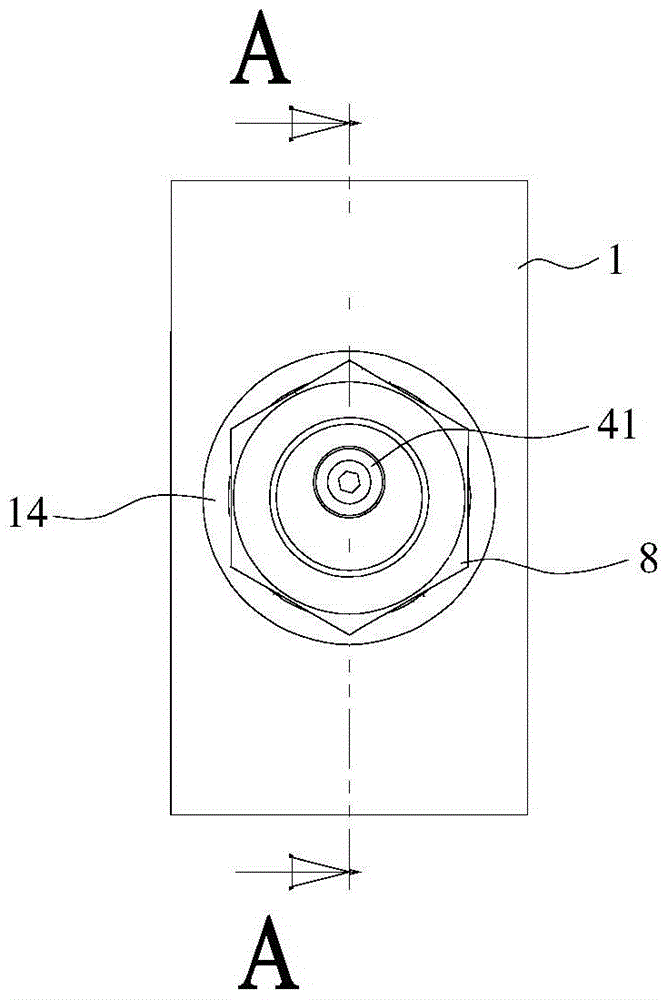
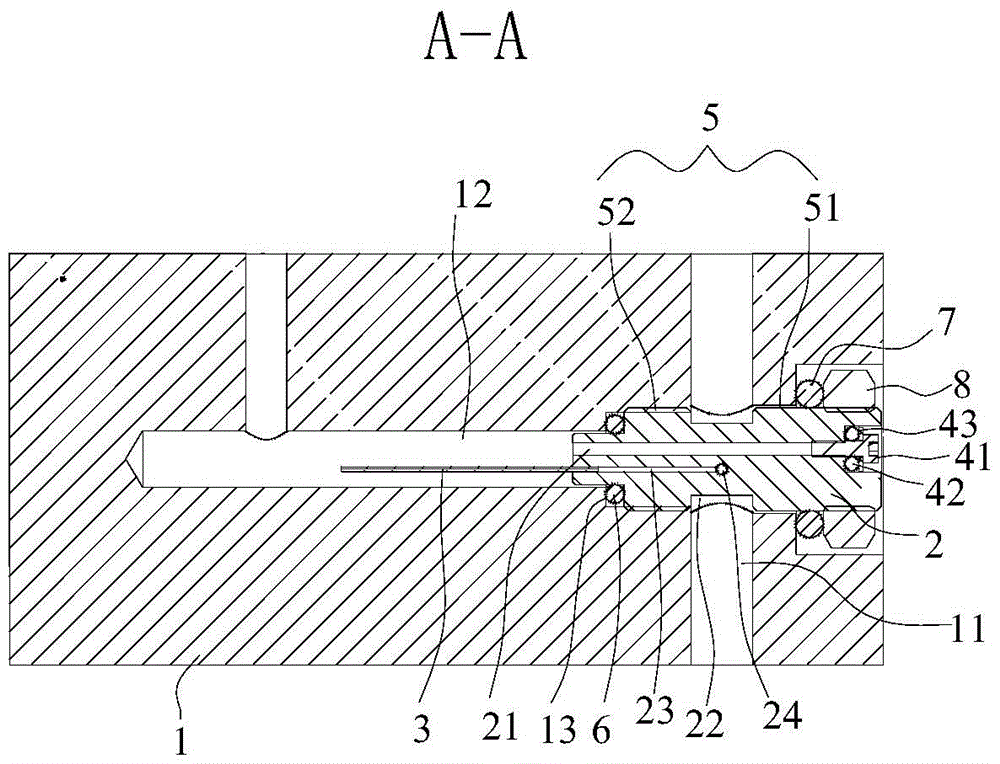
[0017] refer to figure 1 , figure 2 , the present invention provides an easy-to-adjust and easy-to-measure high-precision closed-type constant-pressure static pressure guide rail restrictor, including a shell 1 and a core 2, and the shell 1 is provided with an oil inlet chamber 11 and an oil outlet chamber 12 , the housing 1 is provided with a core body mounting position that respectively intersects with the oil inlet chamber 11 and the oil outlet chamber 12, the core body 2 is installed in the core body installation position, and the core body 2 is provided with Conduct the throttling oil passage of the oil inlet chamber 11 and the oil outlet chamber 12, the core body 2 is connected with a capillary 3 extending into the oil outlet chamber 12 at the outlet of the throttling oil passage, it can be determined through experiments The optimum length of the capillary 3 can be cut off if it is too long, and a longer capillary 3 can be rebonded if it is too short. The capillary 3 ...


PUM


Abstract

The invention discloses an easily-adjusting and easily-measuring high-precision closed type constant-pressure static-pressure guide rail throttling device. The easily-adjusting and easily-measuring high-precision closed type constant-pressure static-pressure guide rail throttling device comprises a shell body and a core body, wherein the shell body is internally provided with an oil inlet cavity and an oil outlet cavity; the shell body is provided with a core body mounting position joined with the oil inlet cavity and the oil outlet cavity; the core body is mounted in the core body mounting position; the core body is provided with a throttling oil path which is used for communicating the oil inlet cavity and the oil outlet cavity; and the outlet of the core body, in the throttling oil path, is connected with a capillary tube stretching into the oil outlet cavity. According to the throttling device, the oil inlet cavity and the oil outlet cavity which are connected with a guide rail oil cavity and an oil supplying system, and the core body mounting position are formed in the shell body respectively; when the throttling device is used, oil liquid enters the oil inlet cavity by the oil supplying system and enters the oil outlet cavity from the capillary tube through the throttling oil path on the core body, so that the throttling is realized. The throttling device has a simple structure and is convenient to detach; and the length of the capillary tube can be adjusted randomly according to requirements, the machining is simple and the cost is low. The core body is directly provided with a detection oil path for detecting the oil pressure of the oil outlet cavity, so that the oil pressure is convenient to detect and the on-line detection can be realized in real time.

Description

technical field [0001] The invention is used in the field of hydraulic throttles, and in particular relates to an easy-to-adjust and easy-to-measure high-precision closed-type constant-pressure static pressure guide rail throttle. Background technique [0002] At present, hydrostatic guide rails are widely used in ultra-precision machine tools. There are multiple oil chambers in the hydrostatic guide rails, and the load of the guide rails is realized by the pressure difference between the upper and lower oil chambers. The hydrostatic guide rail adopts a constant pressure oil supply system, that is, a system that uses an oil pump whose output pressure remains basically constant to supply oil to all oil chambers of the hydrostatic guide rail at the same time. Therefore, each oil chamber must be connected with a restrictor in series, so that the hydrostatic guide rail has the carrying capacity. [0003] The structure of the restrictor can be divided into two types according to...

Claims


Application Information

Patent Timeline
Patent Type & Authority Patents(China)
IPC IPC(8): F16C32/06
Inventor 李克天朱涛刘强陈新陈新度李明泽周春强王晗王哲王素娟
Owner GUANGDONG UNIV OF TECH
Learn More