Multi-stage screw spring transmission

A transmission and spring clutch technology, which is applied in the field of transmission technology and gear transmission, can solve the problems of high efficiency, low transmission clutch efficiency, and impractical transmission efficiency, and achieve the effect of simplification of clutch action and easy shifting operation

Active Publication Date: 2017-01-04
徐州雅居乐环保科技有限公司
View PDF7 Cites 0 Cited by
  • Summary
  • Abstract
  • Description
  • Claims
  • Application Information

AI Technical Summary

Problems solved by technology

[0002] Since the birth of automobiles, human beings have never stopped studying the clutches of automobiles. People have developed a variety of automobile transmissions. Most of the most commonly used transmissions use clutches such as friction clutches, hydraulic coupling clutches or electromagnetic clutches. Gearboxes of different linear velocities produced by gears of different diameters on the same driving shaft realize the speed change, but the clutch efficiency is not high for these speed changers, and the transmission efficiency cannot be as efficient as the gear transmission; the present invention is based on Wei Boqing "2011103608922 Coaxial and co-cylindrical multi-stage forward and reverse transmission method and its device", "201510000063.1 Screw spring synchronizer" and "201510001309.7 Screw spring clutch" three invention patent technologies, "Coaxial and co-cylindrical multi-stage positive and negative The technology of shifting speed method and its device" shifts the input rotational power to the output power wheels of each stage installed on the same shaft with the same outer diameter and the same outer gear, and then passes through the various output wheels installed on the output wheels of each stage The screw spring clutch combines the rotational power of one of the output wheels of each level through the screw and the spring ingeniously, and uses the principle of magnetic attraction to form a non-contact, spring-buffered, no obvious frustration, and gear-like transmission efficiency Equally efficient transmission for power transmission

Method used


Image

  • Multi-stage screw spring transmission
  • Multi-stage screw spring transmission
  • Multi-stage screw spring transmission

Examples


Embodiment Construction

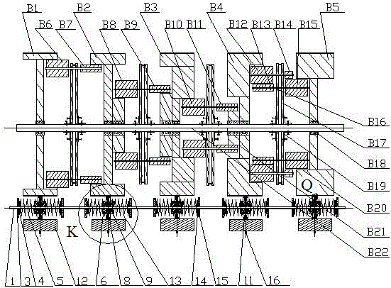
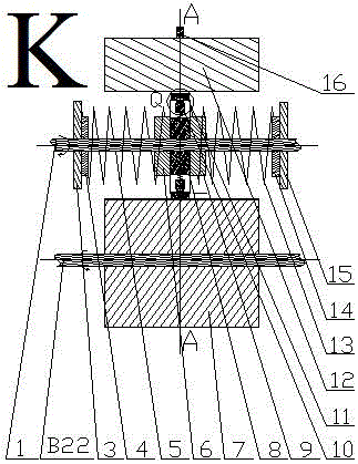
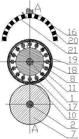
[0019] exist figure 1 In the embodiment shown in -7: the multi-stage screw spring transmission includes a set of coaxial and co-cylindrical multi-stage forward and reverse transmission devices, and multiple sets of screw spring clutches; it is characterized in that: coaxial and co-cylindrical multi-stage positive The reverse transmission device includes a plurality of driven wheels, from left to right are the first-stage driven wheel B1, the second-stage driven wheel B2, the third-stage driven wheel B3, the fourth-stage driven wheel B4 and the fifth-stage driven wheel B5. They are all connected by bearings B18 and installed on the same fixed shaft B22, and the axis lines of the driven wheels at all levels overlap with the axis lines of the fixed shaft B22, and the driven wheels at all levels can rotate on the fixed shaft B22 without driving the fixed shaft B22 Rotating, coaxial and cylindrical multi-stage positive and negative transmission devices have a set of power input pin...


PUM


Abstract

A multi-stage screw rod spring transmission comprises a coaxial co-column multi-stage forward and reverse rotation speed transmission device and multiple screw rod spring clutches, and is characterized in that the coaxial co-column multi-stage forward and reverse rotation speed transmission device comprises multiple driven wheels which include the first-stage driven wheel, the second-stage driven wheel, the third-stage driven wheel, the fourth-stage driven wheel and the fifth-stage driven wheel from left to right, the multiple stages of driven wheels are connected to the same fixing shaft through bearings, and a power input auxiliary gear and a power output auxiliary gear are arranged between every two stages of driven wheels for power transmission; the outer side of each stage of driven wheel is provided with one screw rod spring clutch, each stage of driven wheel is meshed with a passive free wheel of the corresponding screw rod spring clutch, all the screw rod spring clutches are installed on the same driven shaft, but only the passive free wheel of one screw rod spring clutch in all the screw rod spring clutches can be meshed with the corresponding driven wheel to rotate, and disengaging and engaging of the screw rod spring clutches are controlled through magnetic attraction force near and far away from a magnetic half-cylinder outside each passive free wheel.

Description

technical field [0001] The invention relates to a multi-stage screw spring transmission, which is suitable for various mechanisms requiring speed change and speed regulation, such as speed change devices of various vehicles, gearboxes of lathes, etc., and belongs to the technical fields of transmission technology and gear transmission. Background technique [0002] Since the birth of automobiles, human beings have never stopped studying the clutches of automobiles. People have developed a variety of automobile transmissions. Most of the most commonly used transmissions use clutches such as friction clutches, hydraulic coupling clutches or electromagnetic clutches. Gearboxes of different linear velocities produced by gears of different diameters on the same driving shaft realize the speed change, but the clutch efficiency is not high for these speed changers, and the transmission efficiency cannot be as efficient as the gear transmission; the present invention is based on Wei ...

Claims


Application Information

Patent Timeline
Patent Type & Authority Patents(China)
IPC IPC(8): F16H37/12
CPCF16H37/12F16H2702/00
Inventor 魏伯卿
Owner 徐州雅居乐环保科技有限公司
Why Eureka
Try Eureka