
A Method for Obtaining Vibration Stress of Engine Rotor Blades

A technology of rotor blades and vibration stress, which is applied in vibration testing, testing of mechanical components, testing of machine/structural components, etc., can solve the problems of high test cost, high test difficulty, and difficulty in controlling the sound field, and achieve low test cost, Avoid effects where the sound field is difficult to control

Active Publication Date: 2018-03-02
CHINA AIRPLANT STRENGTH RES INST
View PDF3 Cites 0 Cited by
  • Summary
  • Abstract
  • Description
  • Claims
  • Application Information

AI Technical Summary

Problems solved by technology

[0003] It is very important to test the vibration stress of the engine rotor blades under noise excitation, and the test cost of the vibration stress caused by the noise excitation is high when the engine is turned on. It needs a high-power motor drive and expensive ring brushes to lead to the strain signal. At the same time, the test Difficult to control the sound field in the case of rotation

Method used


Image

  • A Method for Obtaining Vibration Stress of Engine Rotor Blades
  • A Method for Obtaining Vibration Stress of Engine Rotor Blades
  • A Method for Obtaining Vibration Stress of Engine Rotor Blades

Examples


Embodiment 1

[0031] The invention provides a method for obtaining the vibration stress of an engine rotor blade, which specifically includes the following steps:

[0032] S1. Using traveling wave sound field to simulate noise excitation;

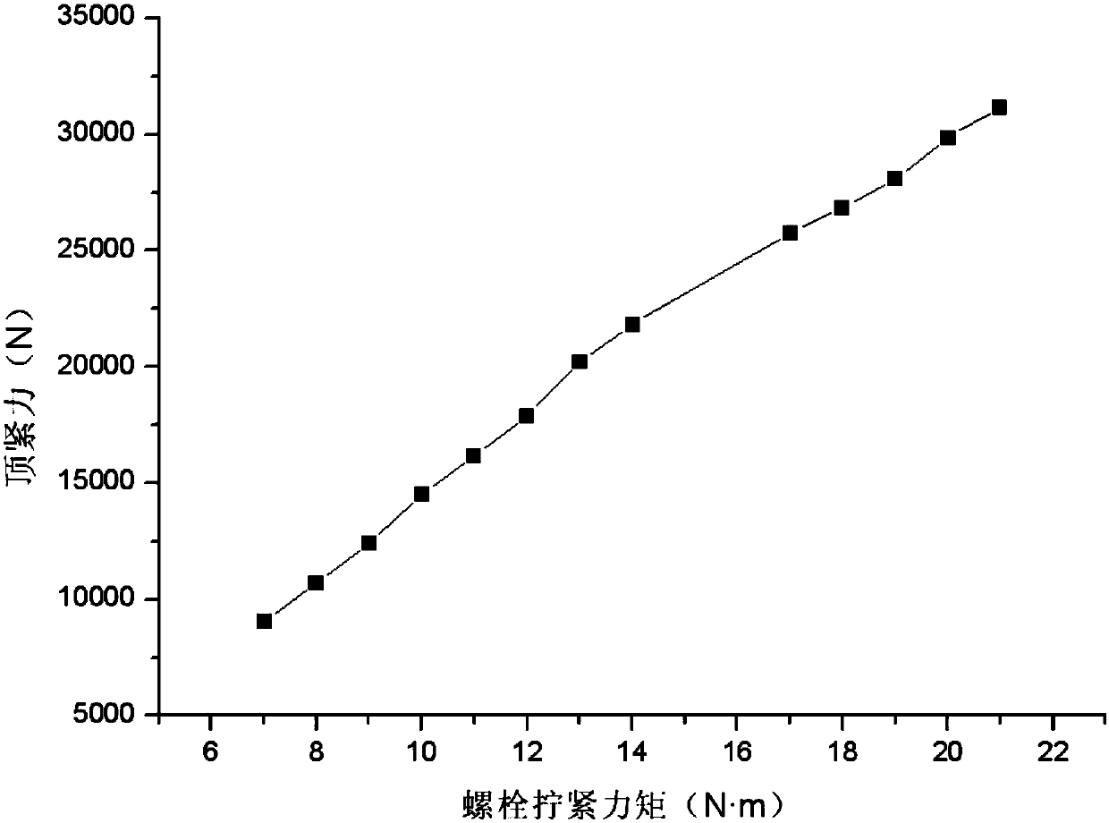
[0033] S2. Use the blade root clamping force method to simulate the blade root force boundary caused by the rotating speed, and install the rotor blade test piece on the fixture according to the blade root force boundary;

[0034] S3. Obtain the maximum root mean square principal stress at the maximum vibration stress part of the rotor blade by means of a dynamic strain test.

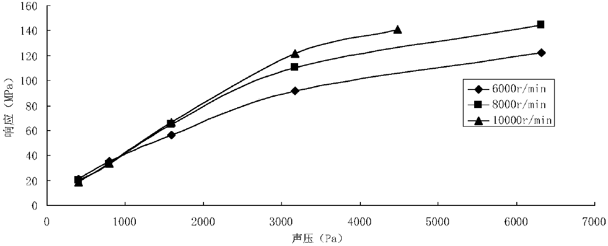
[0035] In this embodiment, in the step S1, the requirements of the test for the noise spectrum are met through the design of the traveling wave tube and the closed-loop control of the sound field, and the requirements for the direction of the noise excitation are met through the design of the installation fixture. Specifically, a circular traveling wave tube with a small cross-se...

Embodiment 2

[0050] Similar to Embodiment 1, the difference is that this embodiment adopts single-frequency sound excitation, including the following steps:

[0051] S1. Using traveling wave sound field to simulate noise excitation;

[0052] S2. Use the blade root clamping force method to simulate the blade root force boundary caused by the rotating speed, and install the rotor blade test piece on the fixture according to the blade root force boundary;

[0053] S3. Obtain the maximum root mean square principal stress at the maximum vibration stress part of the rotor blade by means of a dynamic strain test.

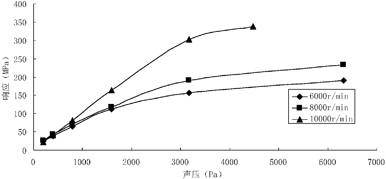
[0054] In this embodiment, in the step S1, the requirements of the test for the noise spectrum are met through the design of the traveling wave tube and the closed-loop control of the sound field, and the requirements for the direction of the noise excitation are met through the design of the installation fixture. Specifically, a circular traveling wave tube with a small cross-section i...


PUM


Abstract

The invention provides a static testing method for obtaining the vibration stress of a rotor vane of an engine under noise excitation. The method comprises the following steps: simulating the noise excitation by using a travelling wave sound field; simulating a vane root force boundary caused by a rotational speed by a vane root jacking force method; obtaining the largest mean square root principal stress at a part with the largest vibration stress of the rotor vane by a dynamic strain testing means. By the method, the vibration stress under the noise excitation and each fixed physical speed of the rotor vane can be tested, the direction of the noise excitation of the rotor vane can be conveniently considered, the experimentation cost is lower, multiple problems, for example, a high-power motor is needed for driving, and a costly annular electric brush is needed to lead out a strain signal which are caused by the fact that a noise excitation test is performed under the situation that the rotor vane rotates are solved, and the problem that the sound field is difficult to control under the situation that the rotor vane rotates is also solved.

Description

technical field [0001] The invention relates to the field of aero-engine structural strength, in particular to a static test method for obtaining vibration stress of engine rotor blades. Background technique [0002] Engine rotor blades are one of the key components of aero-engines, and their working conditions are harsh. The rotor blades not only bear large centrifugal loads and high blade tip speeds when rotating at high speeds, but also are in complex fields coupled with flow fields, temperature fields, and sound fields. Under the working environment, its static stress and dynamic stress levels are relatively high. Vibration stress is one of the main stress states of rotor blades when they are working, and the vibration stress of rotor blades mainly comes from airflow disturbance, noise excitation or vibration transmitted by blade discs. For example, in the document Tao Chunhu et al., Failure and Prevention of Aeroengine Rotating Parts, National Defense Industry Press, I...

Claims


Application Information

Patent Timeline
Patent Type & Authority Patents(China)
IPC IPC(8): G01M13/00G01M7/02G01L5/00
Inventor 王琰郭定文王秋蓉黄文超
Owner CHINA AIRPLANT STRENGTH RES INST
Learn More