Wire harness bundling test plate and application method thereof

A technology for testing boards and wire harnesses, which is applied in the direction of measuring electricity, measuring devices, and measuring electrical variables, etc. It can solve the problems that the wiring tooling cannot be matched, the specifications of the wire harness are difficult to unify, and the production cost is increased, so as to improve the efficiency of bundling and quality, increase the test function, reduce the effect of binding difficulty

Active Publication Date: 2015-04-01
TIANJIN RES INST OF ELECTRIC SCI
View PDF3 Cites 1 Cited by
  • Summary
  • Abstract
  • Description
  • Claims
  • Application Information

AI Technical Summary

Problems solved by technology

[0002] At present, in the process of bundling and testing the wiring harness of the component connecting wires of the power conversion device, in the process of checking the on-off of the wiring harness according to the wiring structure of the device, there are mainly the following technical problems: 1. During the assembly process of the power conversion device Among them, the production and assembly of various components connecting wires and cables takes up more than half of the total assembly time, and the wiring of existing power conversion devices requires trained professionals to operate, which requires high technical requirements for personnel; 2 . Due to the different technical proficiency of personnel, it is difficult to unify the specifications of the wire harnesses made by the existing wiring methods, which cannot meet the increasing demand for product consistency; 3. The existing tooling contains little information or the information is not intuitive. The technical requirements for workers are too high

Method used


Image

  • Wire harness bundling test plate and application method thereof
  • Wire harness bundling test plate and application method thereof
  • Wire harness bundling test plate and application method thereof

Examples


Embodiment Construction

[0036] The present invention will be further described in detail below in conjunction with the accompanying drawings and through specific embodiments. The following embodiments are only descriptive, not restrictive, and cannot limit the protection scope of the present invention.

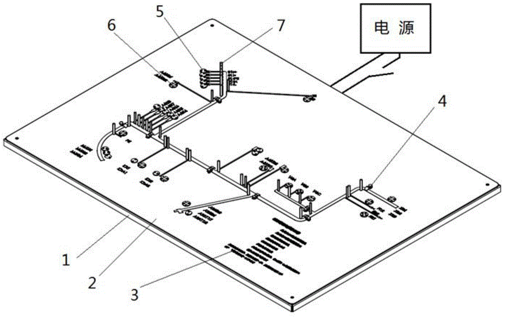
[0037] A wire harness bundling test board, including a metal base 1, a wire harness positioning column 7, a cover plate 2, and a wire harness bundling step image 3 , wire harness fixture 4, positive pole fixture 5, negative pole fixture 6 and power supply, the preset position end of the metal base is fixed with a wire harness positioning column, and the upper end of the metal base is flat and fixed with a cover plate, which corresponds to the position of the wire harness positioning column There are through holes and pass through the wire harness positioning column; there is a layer of wire harness bundling step diagram between the metal base and the cover plate. Important information such as the sp...


PUM


Abstract

The invention relates to a wire harness bundling test plate and an application method thereof. A cover plate is laid and fixedly mounted at the upper end of a metal base; a layer of wire harness bundling step map is clamped between the metal base and the cover plate; through holes are formed in the cover plate correspondingly; a wire harness positioning column and a wire harness clamp used for assisting wire harness positioning as well as a positive pole clamp and a negative pole clamp used for detecting the circuit are mounted in the through holes respectively; the positive pole clamp and the negative pole clamp are connected to a test circuit at the lower end of the metal base respectively; the test circuit is connected to an external power supply through conducting wires. According to the invention, the production efficiency of the wire harness bundling plate is improved; the material cost and the labor cost are reduced; wire harness bundling difficulty is greatly reduced; a testing function is added; bundling errors are reduced; the bundling efficiency and quality are effectively improved; the bundling specification is unified.

Description

technical field [0001] The invention belongs to the field of wire harness bundling of a general power conversion device, and relates to special tooling for making wire harnesses, in particular to a wire harness bundling test board and a method for using the same. Background technique [0002] At present, in the process of bundling and testing the wiring harness of the component connecting wires of the power conversion device, in the process of checking the on-off of the wiring harness according to the wiring structure of the device, there are mainly the following technical problems: 1. During the assembly process of the power conversion device Among them, the production and assembly of various components connecting wires and cables takes up more than half of the total assembly time, and the wiring of existing power conversion devices requires trained professionals to operate, which requires high technical requirements for personnel; 2 . Due to the different technical profici...

Claims


Application Information

Patent Timeline
IPC IPC(8): G01R1/04G01R31/02
Inventor 王玉博王建峰楚子林马骁驰郭磊王欢
Owner TIANJIN RES INST OF ELECTRIC SCI
Why Eureka
Try Eureka