An interlocking mechanism for an upper isolating switch

A technology of isolating switch and operating mechanism, applied in the field of switches, can solve problems such as poor reliability and difficulty in determining the installation position, and achieve the effects of reliable interlocking, simple operation and convenient installation.

Inactive Publication Date: 2016-09-28
中黔电气集团股份有限公司
View PDF6 Cites 0 Cited by
  • Summary
  • Abstract
  • Description
  • Claims
  • Application Information

AI Technical Summary

Problems solved by technology

[0003] The currently used isolating switch interlock is a brake wire, which has the following defects: 1. The installation part is convenient, because the brake wire is relatively long, it is difficult to determine the installation position in the cabinet; 2. Since the brake wire is a flexible accessory, it is difficult to , there will be position changes, so the reliability of the control is poor

Method used


Image

  • An interlocking mechanism for an upper isolating switch
  • An interlocking mechanism for an upper isolating switch
  • An interlocking mechanism for an upper isolating switch

Examples


Embodiment Construction

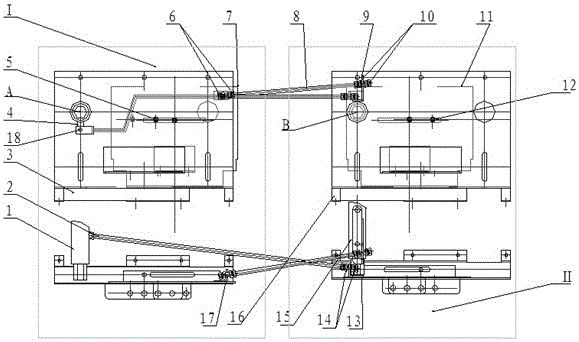
[0018] The present invention will be further described in detail below in conjunction with the accompanying drawings. An interlocking mechanism for an upper disconnector includes: an upper left disconnector operating mechanism I, an upper right disconnector operating mechanism II, a pull rod, an adjusting nut and a pin; it is characterized in that:

[0019] The upper left isolation switch operating mechanism I includes: upper left isolation switch operating shaft 1, left fixing mechanism plate 3, crank arm 4, screw A5, left sliding mechanism plate 7, and curved plate C17;

[0020] The crank arm 4 is welded on the lower side of the upper left isolating switch operating shaft 1, the screw rod A5 and the left sliding mechanism plate 7 are connected to the left fixed mechanism plate 3, and the screw rod A5 can slide in the long waist hole on the left fixed mechanism plate 3, thereby realizing The left and right sliding of the left sliding mechanism plate 7; the curved plate C17 is ...


PUM


Abstract

The invention discloses an interlock mechanism of an upper isolating switch, comprising: an upper left isolating switch operating mechanism (I), an upper right isolating switch operating mechanism (II), a pull rod A (2), a pull rod B (8), and a pin (18) , adjusting nut A (6), adjusting nut B (10), adjusting nut C (15); pull rod A (2) drives the right sliding mechanism plate (11) through the connection of adjusting nut C (14) and curved plate B (13) Slide left and right to make operation hole B open or close; Bending plate A (9), adjusting nut A (6) is connected with pull rod B (8), and pull rod B (8) is connected to bending plate C ( 17) The connection drives the left sliding mechanism plate (7) to slide left and right, so that the operation hole A is opened or closed. The interlock mechanism of the present invention is simple to operate, reliable to interlock and easy to realize specific operation steps.

Description

technical field [0001] The invention relates to a switch, in particular to an interlock mechanism for an upper isolation switch. Background technique [0002] When there is an interlocking relationship between two isolating switches, there are strict operating procedures during power transmission operation and power failure operation. [0003] The currently used isolating switch interlock is a brake wire, which has the following defects: 1. The installation part is convenient, because the brake wire is relatively long, it is difficult to determine the installation position in the cabinet; 2. Since the brake wire is a flexible accessory, it is difficult to , the position will fluctuate, so the reliability of the control is poor. Contents of the invention [0004] The object of the present invention is to provide an interlock mechanism for an upper disconnector to solve the above problems. [0005] In order to solve the above-mentioned technical problems, the present inven...

Claims


Application Information

Patent Timeline
Patent Type & Authority Patents(China)
IPC IPC(8): H01H9/26
CPCH01H31/10
Inventor 彭忠富
Owner 中黔电气集团股份有限公司
Why Eureka
Try Eureka