Channel flow generator applied to remote meter reading system

A remote meter reading system and pipeline flow technology, applied in the field of pipeline flow generators, can solve problems such as potential safety hazards, limited battery life, and frequent replacement, achieving no mechanical shock and noise, strong power generation and power supply capabilities, and improved operation reliability effect

Inactive Publication Date: 2015-04-01
ZHEJIANG NORMAL UNIVERSITY
View PDF9 Cites 20 Cited by
  • Summary
  • Abstract
  • Description
  • Claims
  • Application Information

AI Technical Summary

Problems solved by technology

Although the technology of the above-mentioned meter reading system in terms of data processing and transmission has become more and more mature, there is no report on its actual promotion and application. , there is no pre-laying cable for the automatic meter reading system, and the method of laying temporary open wires is difficult to be accepted by users due to certain potential safety hazards; when the battery is used for power supply, the use time is limited and it needs to be replaced frequently. The collection, processing and sending of information cannot be completed during the replacement

Method used


Image

  • Channel flow generator applied to remote meter reading system
  • Channel flow generator applied to remote meter reading system
  • Channel flow generator applied to remote meter reading system

Examples


Embodiment Construction

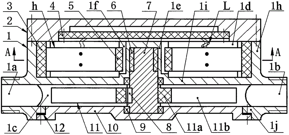
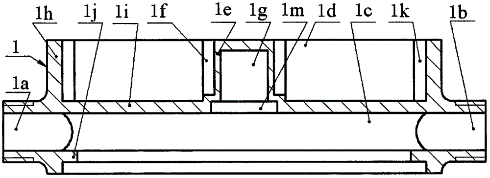
[0013] The partition 1i of the main body 1 divides the main body 1 into a fluid chamber 1c and an energy capture chamber 1d, and the side wall 1j of the fluid chamber 1c is provided with an inlet 1a and an outlet 1b, and the centers of the inlet 1a and the outlet 1b of the fluid chamber 1c are coaxial, The end of the side wall 1j of the fluid cavity 1c is provided with a lower end cover 10 via screws, a gasket 12 is provided between the lower end cover 10 and the end face of the side wall 1j of the fluid cavity 1c, and the center of the lower end cover 10 is inlaid with a bearing 9; Axial pin holes 1k are evenly distributed on the side wall 1h of the energy chamber 1d, the end of the side wall 1h of the energy capture chamber 1d is installed with an upper end cover 2 via screws, and the counterbore boss of the upper end cover 2 is installed with screws. The circuit board 4; the partition 1i of the main body 1 is provided with a round table 1e, the round table 1e is placed in th...


PUM


Abstract

The invention relates to a channel flow generator applied to a remote meter reading system, and belongs to the technical field of power generation. A fluid cavity and an energy harvesting cavity are arranged on a main body, the lateral wall of the fluid cavity is provided with an inlet / outlet and a lower end cover, the lateral wall of the energy harvesting cavity is provided with an axial pin hole and an upper end cover, and the upper end cover is provided with a circuit board; a main body separating plate is provided with a circular truncated cone, the circular truncated cone is provided with an axial guide groove, a bearing hole and a cavity, a main shaft is installed on the lower end cover and the circular truncated cone through a bearing and provided with a magnetic ring and an impeller, a pin shaft and a magnetic block are arranged at the two ends of each piezoelectric vibrator in a riveted mode, the magnetic blocks are arranged in circular truncated cone guide grooves, the pin shafts are arranged in the pin hole of the energy harvesting cavity and pressed through the upper end cover, and the magnetic blocks are installed near the opposite pole of the magnetic ring. The channel flow generator applied to the remote meter reading system has the advantages that pre-bending type piezoelectric vibrators are stimulated through non-contact magnetic coupling for stretching deformation power generation, a movable component is sealed in the fluid cavity and does not leak, the reliability of operation of a circuit system is high, piezoelectric patches only bear pressing stress, mechanical reliability is high, the magnetic ring stimulate the multiple piezoelectric vibrators at the same time, the power generation capacity is high, and noise is avoided.

Description

technical field [0001] The invention belongs to the technical field of energy recovery, and in particular relates to a pipeline flow generator used in a remote meter reading system. Background technique [0002] Natural gas and tap water are indispensable daily consumer goods in the homes of urban residents, and the records and statistics of their consumption are currently mainly done manually. Manual meter reading is not only inefficient and a serious waste of manpower and material resources, but more importantly, meter readers often go back and forth many times in vain because there is no one in the household, which seriously affects the accuracy and real-time performance of data statistics. Therefore, in recent years, people have developed various forms of remote automatic meter reading systems, such as the tap water meter reading system proposed in Chinese patents 201310028760.9 and 200910083183.7, the gas meter reading system proposed in Chinese patents 200810191713.5 a...

Claims


Application Information

Patent Timeline
Patent Type & Authority Applications(China)
IPC IPC(8): H02N2/18
Inventor 王淑云范春涛阚君武孙明礼严梦加费翔
Owner ZHEJIANG NORMAL UNIVERSITY
Why Eureka
Try Eureka