Piezoelectric pipe water flow electric generator

A water current generator, piezoelectric technology, applied in hydroelectric power generation, reaction engine, generator/motor, etc., can solve the problems of frequent replacement, user acceptance, limited battery power supply time, etc., and achieve strong power generation and power supply capabilities , no mechanical shock and noise, and the effect of improving mechanical reliability

Inactive Publication Date: 2015-04-01
ZHEJIANG NORMAL UNIVERSITY
View PDF5 Cites 18 Cited by
  • Summary
  • Abstract
  • Description
  • Claims
  • Application Information

AI Technical Summary

Problems solved by technology

Although the data processing and transmission technology of the above-mentioned meter reading system has become increasingly mature, there is no report on its actual promotion and application. The meter reading system is pre-laid with cables, and the method of laying temporary open wires is difficult to be accepted by users due to certain potential safety hazards. When using battery power supply, the use time is limited and needs to be replaced frequently. Once the battery is low and not replaced in time, the information cannot be completed. The collection, processing and sending of

Method used


Image

  • Piezoelectric pipe water flow electric generator
  • Piezoelectric pipe water flow electric generator
  • Piezoelectric pipe water flow electric generator

Examples


Embodiment Construction

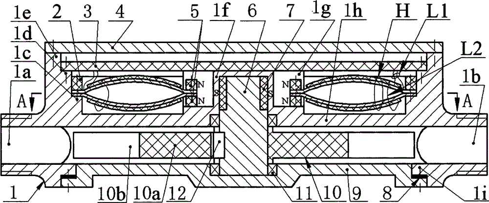
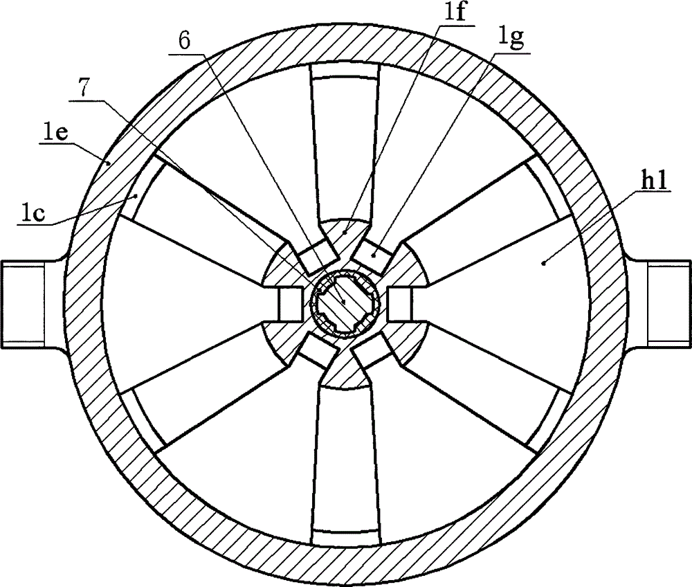
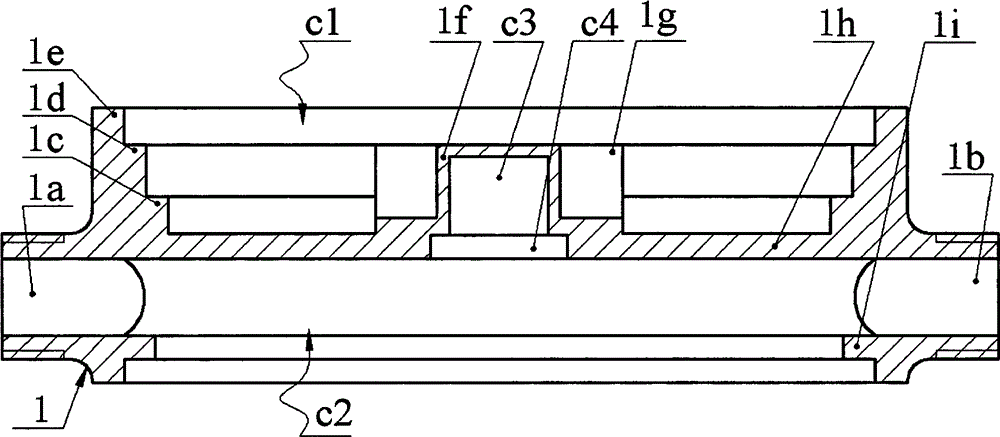
[0011] The partition 1h of the main body 1 divides the main body 1 into an energy capture chamber c1 and a fluid chamber c2; the side wall 1i of the fluid chamber c2 is provided with an inlet 1a and an outlet 1b, and the centers of the inlet 1a and the outlet 1b of the fluid chamber c2 are coaxial; The end of the side wall 1i of the fluid chamber c2 is provided with a lower cover 9 via screws, a gasket 8 is provided between the lower cover 9 and the end face of the side wall 1i of the fluid chamber c2, and a bearing 11 is embedded in the center of the lower cover 9; The inner side of the outer wall 1e of the energy chamber c1 is provided with a boss 1d and a boss 2 1c, and the center of the partition 1h of the main body 1 is provided with a round table 1f, and the round table 1f is placed in the energy capture chamber c1, and on the outer wall of the round table 1f The guide grooves 1g are evenly distributed, and the center of the round platform 1f is provided with a cavity c3 ...


PUM


Abstract

The invention relates to a piezoelectric pipe water flow electric generator, and belongs to the technical field of electric generation. A fluid cavity and an energy capturing cavity are formed in a body, an inlet and an outlet are formed in the side wall of the fluid cavity, and a lower cover is installed at the end of the side wall of the fluid cavity; an upper cover is installed at the end of the side wall of the energy capturing cavity, a circuit board and transducers with magnetic blocks installed at the ends are installed on two steps on the inner side of the side wall of the energy capturing cavity, and each transducer is formed by two bent piezoelectric vibrators; a boss is arranged on a partition plate of the body and provided with guide grooves, a bearing hole and a cavity, and the magnetic blocks are arranged in the guide grooves of the boss; a main shaft is installed on the lower cover and the boss through bearings and provided with a magnetic ring and an impeller, and the magnetic blocks and the magnetic ring are installed in the mode that polarity-opposite magnetic poles are close. The piezoelectric pipe water flow electric generator has the advantages that the pre-bent piezoelectric vibrators are stimulated through non-contact magnetic coupling to be deformed for electric generation, movement parts are sealed in the fluid cavity, leakage is avoided, and a circuit system is high in running stability; piezoelectric plates only bear pressure stress, so that the mechanical reliability is high; the multiple piezoelectric vibrators are stimulated by the magnetic ring at the same time, the electric generation capacity is high, and noise is avoided.

Description

technical field [0001] The invention belongs to the technical field of energy recovery, and in particular relates to a piezoelectric pipeline water flow generator, which is used for power supply of a running water meter reading system. Background technique [0002] Tap water is an indispensable daily consumer product in the homes of urban residents, and the recording and statistics of its consumption are currently mainly done manually. The current manual meter reading operation is not only inefficient and wastes manpower and material resources, but more importantly, meter readers often go back and forth many times in vain because there is no one in the household, which seriously affects the accuracy and real-time performance of data statistics. Therefore, in recent years, people have developed various forms of tap water meter reading systems, such as Chinese patents 201310028760.9 and 200910083183.7. Although the data processing and transmission technology of the above-ment...

Claims


Application Information

Patent Timeline
Patent Type & Authority Applications(China)
IPC IPC(8): H02N2/18F03B3/00
CPCY02E10/20
Inventor 王淑云范春涛蒋永华阚君武严梦加李凝
Owner ZHEJIANG NORMAL UNIVERSITY
Why Eureka
Try Eureka