Air Gun and Firing Stop Control Method

a technology of air gun and control method, which is applied in the field of electronic control of air guns, can solve the problems of inability to control how many times the gun was shot, defective operation, and easy defective operation due to burnt contacts or incomplete contacts, so as to prevent degradation of the spring effect of the spring, improve the reliability of the mechanical mechanism of the gun, and facilitate the inside of the gun

Inactive Publication Date: 2006-11-02
TSURUMOTO KOICHI
View PDF0 Cites 30 Cited by
  • Summary
  • Abstract
  • Description
  • Claims
  • Application Information

AI Technical Summary

Benefits of technology

[0013] In order to solve the aforementioned problems, the object of the present invention is to improve the reliability of the mechanical mechanism of the gun, prevent degradation of the spring effect of the spring and make it possible to easily open the inside of the gun to perform maintenance by performing control after any number of shootings so that the rotating shaft (sector gear) and rack do not stop in the meshed state.

Problems solved by technology

In the aforementioned prior art, starting and stopping the shooting operation was performed by turning ON / OFF a mechanical switch to the power supply of the motor, so there was a problem in reliability in that defective operation due to burnt contacts or incomplete contacting occurs easily.
Also, switching between single-shot mode and repeating mode is performed by a mechanism comprising a mechanical cam and lever, so defective operation occurs easily due to wear or fatigue.
Moreover, in the repeating mode operation of this prior art, it was not possible to control how many times the gun was shot.
Also, in this prior art, there was no way for checking whether or not there were bullets in the magazine, and particularly during continuous shooting, even after the last bullet was shot, there was a problem in that in a state of having no bullets, useless blank shooting continued.
Therefore, there was a problem in that the rotating shaft (sector gear) also stopped at an arbitrary position, and stopped while still being meshed with the rack formed on the piston.
(1) The air gun is left for a long period of time in the stopped state with stress still being applied to the rotating shaft and rack, which causes mechanical failure of the deceleration mechanism and piston unit to occur.
Therefore, the spring effect of the spring becomes weak.
(3) The air gun is stopped with stress still being applied to the rotating shaft and rack, so the meshing between the rotating shaft and rack cannot be easily released.
Therefore, it is not possible to easily open up the inside when performing internal inspection such as during maintenance.

Method used

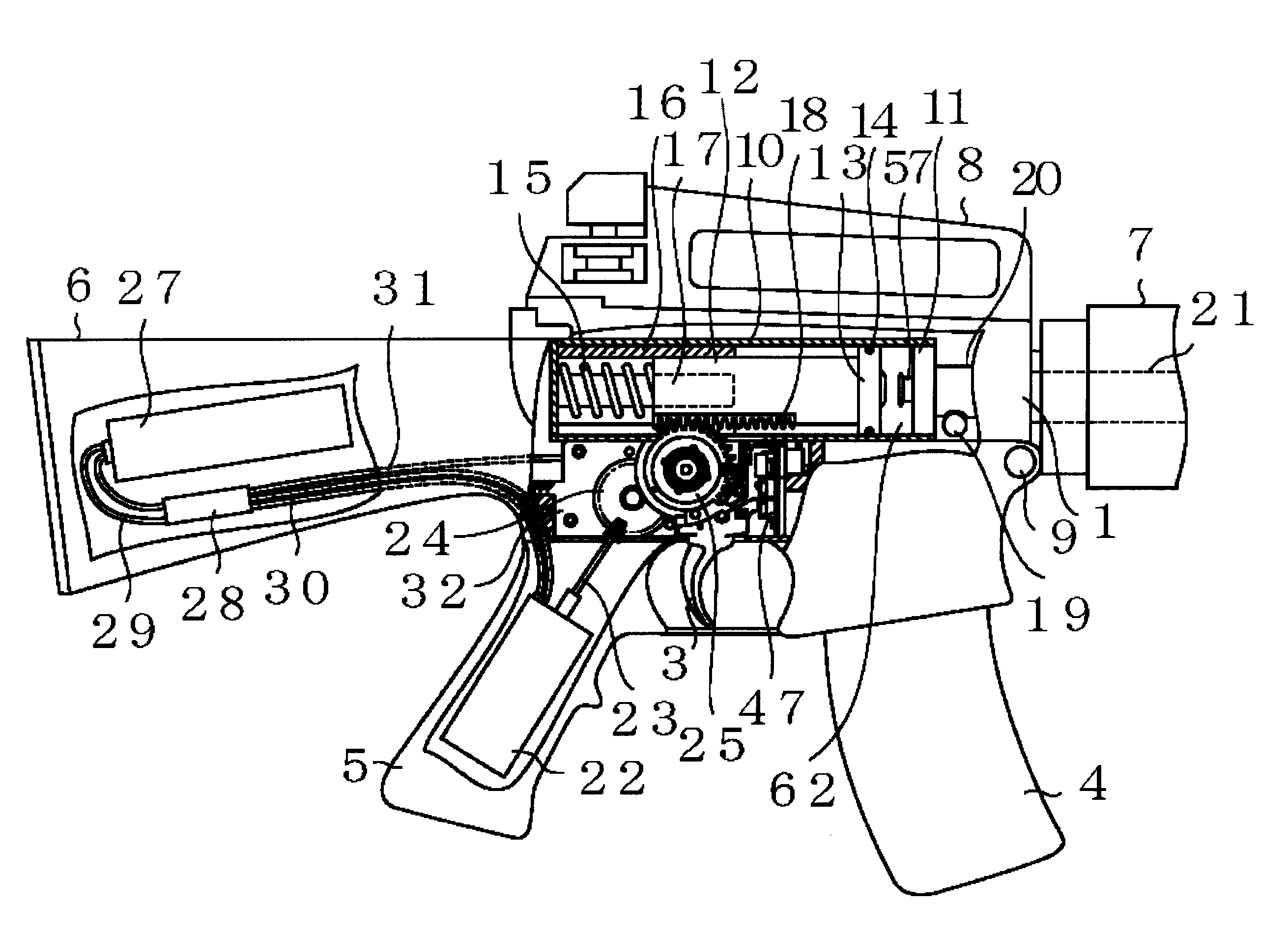
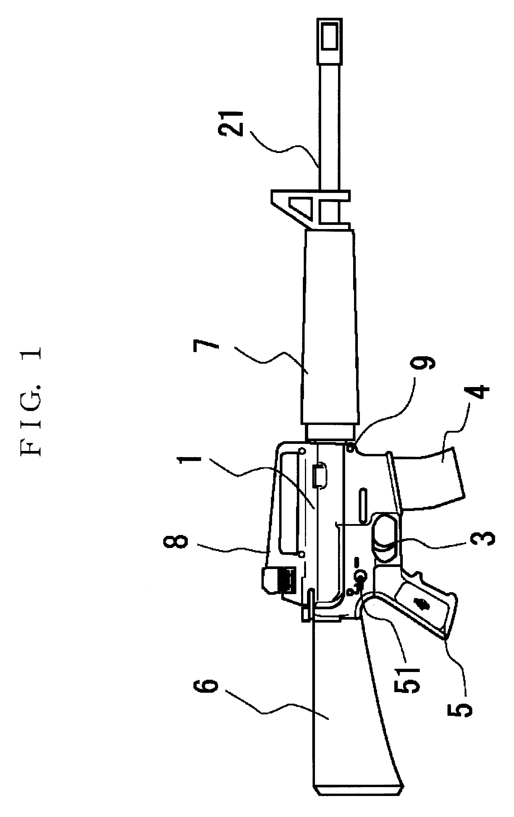
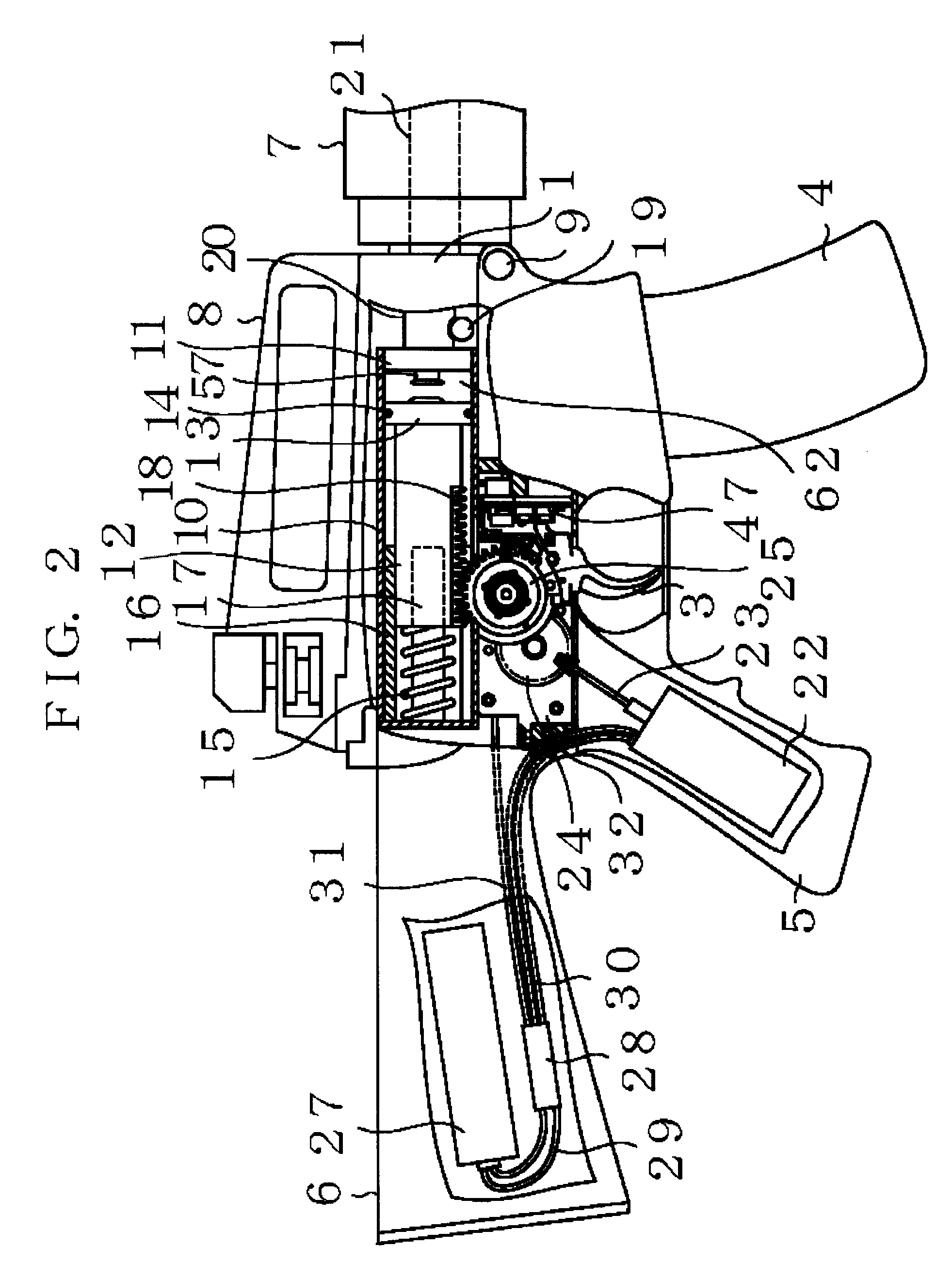

Image

  • Air Gun and Firing Stop Control Method
  • Air Gun and Firing Stop Control Method
  • Air Gun and Firing Stop Control Method

Examples


first embodiment

of Control

[0078] Next, control flowcharts will be used to explain the bullet shooting control in detail.

[0079]FIG. 9 shows a first embodiment of control, and is a flowchart showing control of the single-shot mode operation.

[0080] First, control is started in step 100, and in step 101 a check is performed to determine whether the trigger switch 37 has been pressed. When the trigger switch 37 has not been pressed, a watchdog timer WDT is cleared in step 102, and operation returns to step 101.

[0081] When the microcomputer 49 is operating properly, this watchdog timer WDT is periodically reset in order that an error signal is not output, however, when the microcomputer 49 is not operating properly, the watchdog timer WDT is no longer reset periodically, but outputs an error signal and stops operation by causing a safety apparatus to function, etc. The timer value of the watchdog timer WDT is set to 1000 ms for example when the power to the microcomputer 49 is initially turned ON. The...

second embodiment

of Control

[0094]FIG. 11 shows a second embodiment of control, and is a flowchart of the control for the repeating mode operation.

[0095] First, control is started in step 120, and in step 121 a check is performed to determine whether the trigger switch 37 is pressed. When the trigger switch 37 is not being pressed, then in step 122 a watchdog timer WDT is cleared and operation returns to step 121.

[0096] In step 121, when it is detected that the trigger switch 37 is being pressed, then in step 123 a check is performed to determine whether there are bullets 19 in the magazine 4. This check is executed by inputting a signal from the bullet-detection switch 41 to the microcomputer 49 and checking whether the signal is ON or OFF. When there are bullets 19 in the magazine 4, the pressure member 42 for the bullet-detection switch pushes the bullet-detection switch 41 upward so that the switch is OFF.

[0097] In step 123 when it is detected that there are no bullets 19 in the magazine 4, op...

third embodiment

of Control

[0107]FIG. 12 shows a third embodiment of control, and is a flowchart for N-repeating mode control that is performed when performing the repeating mode operation N times. N can be any arbitrary positive integer 2 or greater. The inventors manufactured a gun with N as 3, however it is not limited to this.

[0108] First, control is started in step 140, and in step 141 a check is performed to determine whether the trigger switch 37 is being pressed. When the trigger switch 37 is not being pressed, then in step 122, the watchdog timer WDT is cleared and operation returns to step 121.

[0109] In step 141, when it is detected that the trigger switch 37 is being pressed, then in step 143 a check is performed to determine whether there are bullets 19 in the magazine 4. This check is executed by inputting a signal from the bullet-detection switch 41 to the microcomputer 49, and checking whether this signal is ON or OFF. When there are bullets 19 in the magazine 4, the pressure member...


PUM


Abstract

The present invention relates to electronic control of an air gun in the form of a model gun, and that after any kind of shooting operation performs control so that a rotating wheel (sector gear) returns to a position where it does not mesh with a rack, and in so doing, improves the reliability of the mechanical mechanism of the gun, prevent degradation of the spring effect of the spring, and furthermore makes it possible to open the inside of the gun and to perform maintenance easily. The air gun comprises: a rack (18) that is located so that it is integrated with a piston (12); a sector gear (25) having a toothed section (33) on part of its circumference that meshes with the rack (18), and a non-toothed section (34) that does not mesh with the rack (18); a motor that drives the sector gear (25) by way of a deceleration-gear mechanism; a rotation-reference position (40) that is located on the sector gear (25); and a sensor (39), (44) that detects the rotation-reference position (40); where when the sensor (39), (40) detects the rotation-reference position (40) (FIG. 6(c)), power to the motor is turned OFF; the sector gear (25) stops at a position where the non-toothed section (34) of the sector gear (25) faces the rack (18) (FIG. 6(d)); and the piston (12) always returns to the starting position of the shooting operation.

Description

BACKGROUND OF THE INVENTION [0001] 1. Field of the Invention [0002] This invention relates to an air gun in the form of a model gun, and particularly to the electronic control of an air gun that is suitable for performing control so that the position of the piston after shooting returns to a specified position regardless of whether shooting was single-shot mode or repeating mode. [0003] 2. Description of the Related Art [0004] An air gun in the form of a model gun that is patterned after an automatic rifle is used as a toy or for shooting practice. Particularly, in the case of being used for shooting practice, it is desired that the air gun have the same appearance and be capable of being handled the same as a real gun. Prior art for this kind of air gun has been disclosed in Japanese Examined Patent Publication H7-43238. [0005] In this prior art, by pulling the trigger, a motor drives a pump comprising a piston and cylinder, and discharges compressed air though a discharge hole, wh...

Claims


Application Information

Patent Timeline
Patent Type & Authority Applications(United States)
IPC IPC(8): F41B11/00F41A19/66F41B11/55F41B11/57F41B11/642F41B11/646
CPCF41A19/66F41B11/55F41B11/646F41B11/642F41B11/57
Inventor TSURUMOTO, KOICHI
Owner TSURUMOTO KOICHI
Why Eureka
Try Eureka