Coal dry-distillation device and modified coal production equipment using same

A technology for manufacturing equipment and coal dry distillation, which is applied in the fields of coal dry distillation devices and upgraded coal manufacturing equipment, can solve problems such as temperature reduction, and achieve the effect of inhibiting the increase of mercury concentration

Inactive Publication Date: 2015-04-01
MITSUBISHI HEAVY IND LTD
8 Cites 0 Cited by

AI-Extracted Technical Summary

Problems solved by technology

[0013] In addition, although the inside of the inner cylinder (body trunk) of the coal pyrolysis device of the rotary kiln system is covered by the outer cylinder (outer skin), the portion (the center in the axial direction) heated by the heati...

Method used

In addition, since the waste that is separated and recovered from the exhaust air 19 sent out from the tower main body 141 of the deactivation treatment device 140, that is, the pulverized coal 4a, can be easily suppressed at a very low cost. Describe the rise in mercury concentration in retorted coa...

Abstract

A rotary kiln-type coal dry-distillation device (120) that: rotatably supports an inner tube (112) inside an outer tube (113); supplies heating gas (17) to the interior of the outer tube (113); moves dried coal (2) from one end side of the inner tube (112) to the other end side, and agitates and dry-distills the dried coal (2) under heat by supplying the dried coal (2) from the one end side of the inner tube (112) to the interior, and rotating the inner tube (112); sends out dry-distilled coal (3) and dry-distilled gas (14) from the other end side of the inner tube (112); and has provided therein a pulverized coal supply device (170) that supplies pulverized coal (4a) having a particle diameter of no more than 100 mu m to the interior of the inner tube (112), such that the volume of the pulverized coal is 1-10 wt% relative to the amount of dry-distilled coal (3) sent from the other end side of the inner tube (112).

Application Domain

BiofuelsSolid fuels +1

Technology Topic

CoalProduct gas +4

Image

  • Coal dry-distillation device and modified coal production equipment using same
  • Coal dry-distillation device and modified coal production equipment using same
  • Coal dry-distillation device and modified coal production equipment using same

Examples

  • Experimental program(7)

Example

[0036] (first embodiment)
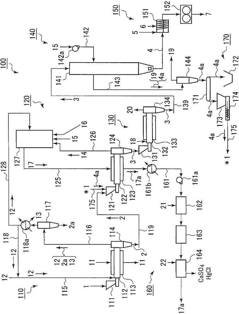
[0037] in accordance with figure 1 , 2 A first embodiment of the coal pyrolysis apparatus of the present invention and the upgraded coal production facility using the coal pyrolysis apparatus will be described.
[0038] like figure 1 As shown, the coal drying mechanism 110 for drying low-rank coal (inferior coal) 1, which is a coal with a high moisture content such as lignite and sub-bituminous coal, ie, a coal drying device 110, includes: a funnel 111, which receives the low-rank coal 1; A cylinder (main body trunk) 112, which is rotatably supported and supplies the low-rank coal 1 in the hopper 111 from one end side (basal end side) to the inside; an outer cylinder (skin) 113, which is so The inner cylinder 112 is rotatable and fixedly supported by covering the outer peripheral surface of the inner cylinder 112, and the heating medium, namely the steam 11, is supplied to the inside (between the inner cylinder 111); The cylinder 112 is rotatably connected to the other end side (front end side) of the inner cylinder 112, and the dried coal 2 is dropped downward from the other end side (front end side) of the inner cylinder 112 and sent out.
[0039] A front end side of an inert gas feed line 115 for feeding an inert gas 12 such as nitrogen gas is connected to one end side (base end side) of the inner cylinder 112 of the coal drying apparatus 110 . One end side of an exhaust line 116 for exhausting the inert gas 12 containing carbon monoxide, water vapor, and the like is connected to the upper portion of the blanking port 114 . A cyclone 117 is connected to the other end side of the exhaust line 116 , and the cyclone 117 separates and recovers the pulverized coal 2 a produced by drying the low-rank coal 1 from the inert gas 12 .
[0040] The cyclone 117 is connected to one end side (base end side) of the circulation line 118 including a condenser 118a for condensing the water vapor in the inert gas 12 after the separation of the pulverized coal 2a. It was shrunk to water 13 and separated and removed. The other end side (front end side) of the circulation line 118 is connected to the middle of the inert gas feed line 115 .
[0041] The lower part of the blanking port 114 of the coal drying device 110 is connected to the upstream side in the conveying direction of a dry coal conveying line 119 such as a belt conveyor, and the dry coal conveying line 119 is used for conveying the coal sent from the blanking port 114. The dry coal 2. The dry coal transfer line 119 is connected to a coal dry distillation apparatus 120 for dry distillation of the dry coal 2 on the downstream side in the transport direction.
[0042] like figure 1 , 2As shown, the coal dry distillation apparatus 120 includes: a funnel 121 that receives the dry coal 2 from the dry coal conveying line 119; The dry coal 2 in the funnel 121 is supplied from one end side (base end side) to the inside; the outer cylinder (skin) 123 is fixed so that the inner cylinder 122 is rotatable and covers the outer peripheral surface of the inner cylinder 122 support, the heating medium, that is, the heating gas 17, is supplied to the inside (between the inner cylinder 121); side), the carbonized coal 3 subjected to carbonization is dropped downward from the other end side (front end side) of the inner cylinder 122 and sent out.
[0043] like figure 1 As shown, one end side (base end side) of an exhaust line 126 is connected to the upper part of the blanking port 124 of the coal dry distillation device 120, and the exhaust line 126 is used to discharge carbon monoxide, water vapor, tar, etc. for dry distillation. Gas (thermal decomposition gas) 14 . The other end side (front end side) of the exhaust line 126 is connected to a combustion furnace 127 to which the air 15 and the combustion aid 16 are supplied.
[0044] An extraction line 128 is connected to the combustion furnace 127, and the extraction line 128 extracts a part of the inert gas 12 after removing the water 13 through the circulation line 118 from the circulation line 118 of the coal drying device 110, and supplied to the combustion furnace 127 . Further, one end side (base end side) of a heating gas feed line 125 for feeding the heating gas 17 generated in the combustion furnace 127 is connected to the combustion furnace 127 . The other end side (front end side) of the heating gas feed line 125 is connected to the inner side of the outer cylinder 123 .
[0045] Below the discharge port 124 of the coal dry distillation apparatus 120 is connected a cooling device 130 , which is a dry distillation coal cooling mechanism, and the cooling device 130 cools the dry distillation coal 3 sent from the discharge port 124 . The cooling device 130 includes: a funnel 131 that receives the dry distillation coal 3 from the blowing port 124 of the coal dry distillation device 120; an inner cylinder (main body trunk) 132 that is rotatably supported and that The pyrolysis coal 3 in the funnel 131 is supplied to the inside from one end side (base end side), and cooling water 18 is sprayed inside; The inner cylinder 132 is fixedly supported in the manner of the outer peripheral surface of the inner cylinder 132; and the blanking port 134 is connected to the other end side (front end side) of the inner cylinder 132 in a rotatable manner, and discharges the cooled pyrolysis coal. 3 is dropped and sent downward from the other end side (front end side) of the inner tube 132 .
[0046] The lower part of the blanking port 134 of the cooling device 130 is connected to the upstream side in the conveying direction of a pyrolysis coal conveying line 139 such as a belt conveyor, and the pyrolysis coal conveying line 119 is used for conveying the material sent out from the blanking port 134. Describe dry distillation coal 3. The downstream side in the conveyance direction of the pyrolysis coal conveyance line 139 is connected to the upper part of the tower main body 141 of the deactivation treatment device 140 , which is an inactivation treatment mechanism for inactivating the pyrolysis coal 3 . An air supply line 142 including a blower 142 a is connected to the tower main body 141 , and the blower 142 a is used to supply the air 15 , which is an oxygen-containing gas, to the inside of the tower main body 141 .
[0047] The lower part of the tower body 141 of the inactivation treatment device 140 is connected to a kneading mechanism, that is, a kneading device 151 , and the kneading device 151 deactivates the modified coal 4 , the binder 5 such as starch and water. 6 Make mixing. The kneading device 151 is connected to a compression device 152 that is a compression mechanism, and the compression device 152 compresses the reformed coal 4 kneaded with the binder 5 and the water 6 to form briquette coal 7 .
[0048] In addition, one end side (basal end side) of an exhaust air line 143 is connected to the tower main body 141 of the inactivation treatment device 140 , and the exhaust air line 143 is sent from the inside of the tower main body 141 to distil the pyrolysis coal. 3. The oxygen-containing air that has undergone inactivation treatment is the exhaust air 19 . The other end side (front end side) of the exhaust air line 143 is connected to a cyclone 144 that separates and recovers the pulverized coal 4 a in the exhaust air 19 .
[0049] A pulverized coal conveying device 171 is connected below the cyclone 144 of the inactivation treatment device 140 , and the pulverized coal conveying device 171 is carried out from the cyclone 144 and separated from the exhaust air 19 . of the pulverized coal 4a. One side of the pulverized coal conveying device 171 ( figure 1 The center is the right side) is connected to the recovery container 172 for recovering the coal dust 4a.
[0050] The other side of the pulverized coal conveying device 171 ( figure 1 The left side in the middle) is connected to the funnel 173 for receiving the coal powder 4a. The lower part of the said hopper 173 is connected to the base end side of the feeder 174 which feeds out the said pulverized coal 4a in this hopper 173 quantitatively. The front end side of the feeding device 174 is connected to the funnel 121 of the coal dry distillation device 120 through a conveyor belt 175 .
[0051] To the outer cylinder 113 of the coal dry distillation apparatus 120 is connected one end side (basal end side) of an exhaust line 161 including a sending blower 161 a that discharges the heating gas 17 from the inside of the outer cylinder 113 the exhaust 17a. The exhaust line 161 is provided with a condenser 161b for cooling the exhaust gas 17a.
[0052] The other end side (front end side) of the exhaust line 161 is connected to a gas receiving part of a denitration mechanism, that is, a denitration device 162 that sprays the ammonium chloride aqueous solution 21 into the exhaust gas 17a. The gas sending part of the denitration device 162 is connected to a gas receiving part of an electric bag filter 163, which is a dust removal mechanism, and the electric bag filter 163 is used to separate and remove dust and the like in the exhaust gas 17a. The gas sending part of the electric bag filter 163 is connected to the gas receiving part of the desulfurization mechanism, that is, the desulfurization device 164, and the desulfurization device 164 blows the calcium carbonate slurry 22 into the exhaust gas 17a. The gas delivery part of the desulfurization device 164 is connected to the outside of the system.
[0053] In the present embodiment described above, the funnel 111 , the inner cylinder 112 , the outer cylinder 113 , the blanking port 114 , the inert gas feeding line 115 , the exhaust line 116 , the The cyclone 117, the circulation line 118, the dry coal conveying line 119, etc. constitute the coal drying device 110, and the hopper 121, the inner cylinder 122, the outer cylinder 123, and the blanking port 124. The heating gas feed line 125, the exhaust line 126, the combustion furnace 127, and the extraction line 128 constitute a coal dry distillation device 120, which consists of the funnel 131, the inner cylinder 132, the The outer cylinder 133, the blanking port 134, the dry coal conveying line 139, etc. constitute the cooling device 130, and the tower body 141, the air supply line 142, the exhaust air line 143, and the The cyclone 144 and the like constitute the inactivation treatment device 140, and the kneading device 151 and the compression device 152, etc. constitute the briquette coal production mechanism, that is, the briquette coal production device 150. The denitration device 162 , the electric bag filter 163 , the desulfurization device 164 , etc. constitute an exhaust gas treatment device 160 , which is an exhaust gas treatment device 160 . The feeding device 174, the conveyor belt 175 and the like constitute a pulverized coal supply device 170, which is a pulverized coal supply mechanism, and the coal drying device 110, the coal dry distillation device 120, the cooling device 130, the inactivation process The apparatus 140 , the briquette coal production apparatus 150 , the exhaust gas treatment apparatus 160 , the pulverized coal supply apparatus 170 , and the like constitute the reformed coal production facility 100 .
[0054] Next, the core operation of the above-mentioned reformed coal production facility 100 will be described first.
[0055] The steam 11 is supplied into the outer cylinder (skin) 123 of the coal drying device 110, the low-rank coal 1 (average particle size: about 10 mm) is put into the funnel 111, and the low-rank coal 1 After supplying the inert gas 12 into the inner cylinder (main body) 112 and feeding the inert gas 12 into the inner cylinder 112, the low-rank coal 1 rotates with the rotation of the inner cylinder 112 while stirring from the inner cylinder 112. One end side of 112 moves to the other end side, so that heating and drying (about 150 to 200° C.) can be performed without omission to form dry coal 2 (average particle size: about 5 mm), which is sent out through the blanking port 114 to the The dry coal transfer line 119 is supplied to the hopper 121 of the coal dry distillation apparatus 120 .
[0056] The inert gas 12 (about 150 to 200° C.) sent to the inner cylinder 112 of the coal drying device 110 and the coal powder 2a (particle size: 100 μm or less) and water vapor are sent from above the blanking port 114 through the exhaust line 116 to the cyclone separator 117, and the above-mentioned pulverized coal 2a is separated and sent to the circulation Line 118, which uses the condenser 118a for cooling, separates and removes water 13, and then returns most of it (about 85%) to the inert gas feed line 115, where it is sent to the inert gas again with new inert gas 12 The inner cylinder 112 is recycled, and on the other hand, a part (about 15%) thereof is sent to the combustion furnace 127 of the coal dry distillation apparatus 120 through the extraction line 128 .
[0057] The dry coal 2 (about 150 to 200° C.) supplied to the funnel 121 of the coal dry distillation apparatus 120 is fed into the inner cylinder (main body trunk) 122 , and the inner cylinder 122 rotates while the dry coal 2 (about 150 to 200° C.) The inner cylinder 122 moves from one end side to the other end side while stirring, and uses the heating gas 17 (about 1000 ppm) which is fed from the combustion furnace 127 to the outer cylinder (skin) 123 through the heating gas feeding line 125 . ~ 1100° C.) without omission, and thermally dry distillation (350 to 450° C.) is carried out to form dry distillation coal 3 (average particle size: about 5 mm), which is supplied to the funnel 131 of the cooling device 130 through the blanking port 124 Inside.
[0058] The dry distillation gas 14 (about 350 to 450° C.) generated in the inner cylinder 122 of the coal dry distillation apparatus 120 along with dry distillation is fed from above the discharge port 124 through the exhaust line 126 The combustion furnace 127 is combusted with the inert gas 12 (including carbon monoxide, etc.) and the air 15 (which may also contain the oxidant 16 as needed) to generate the heating gas 17 .
[0059] The pyrolysis coal 3 (350 to 450° C.) supplied to the hopper 131 of the cooling device 130 is fed into the inner cylinder (body trunk) 132 , and is stirred while the inner cylinder 132 rotates. Since the inner cylinder 132 moves from one end side to the other end side, the cooling water 18 sprayed into the inner cylinder 132 is completely cooled (about 50 to 60° C.), and then passes through the blanking port 134 It is sent to the pyrolysis coal conveyance line 139, and is supplied to the inside of the tower main body 141 of the inactivation treatment device 140 from above.
[0060] The cooling water 18 sprayed into the inner cylinder 132 of the cooling device 130 is vaporized along with the cooling of the dry distillation coal 3 to form water vapor 20 which is sent to the outside of the system from above the blanking port 134 .
[0061] Active points (radicals) generated by dry distillation of the dry distillation coal 3 (about 50 to 60° C.) supplied from the upper part of the tower main body 141 of the inactivation treatment device 140 are fed from the air to The oxygen in the air 15 of the blower 142a of the line 142 reacts and is inactivated to form a reformed coal 4 (average particle size: about 5 mm), which is sent from the lower part of the tower main body 141 to the kneading device 151.
[0062]The exhaust air 19 (about 50 to 70° C.) used for the inactivation treatment of the pyrolysis coal 3 and the coal dust 4 a produced by the inactivation treatment in the inside of the tower main body 141 of the inactivation treatment device 140 (Particle size: 100 μm or less) is sent to the cyclone 144 through the exhaust air line 143, and the pulverized coal 4a is separated and discharged to the outside of the system.
[0063] The reformed coal 4 (about 30° C.) sent to the kneading device 151 is kneaded together with the binder 5 and the water 6 , and then sent to the molding device 152 for compression molding. Formed coal 7 is formed.
[0064] When the briquette coal 7 is produced from the low-rank coal 1 in this way, when the dry coal 2 is dry distilled, the dry distillation gas 14 will contain a trace amount of HgS or HgCl 2 gases such as mercury.
[0065] Here, in the above-mentioned rotary kiln type coal dry distillation apparatus 120 , the inner cylinder 122 is not covered with the outer cylinder 123 and protrudes from the outer cylinder 123 and cannot be heated by the heating gas 17 . A portion (the other end side in the axial direction) has a temperature drop. Therefore, conventionally, the portion of the inner cylinder 122 which is not covered by the outer cylinder 123 and protrudes from the outer cylinder 123 and cannot be heated by the heating gas 17 (the other end side in the axial direction) releases the mercury Such substances are adsorbed on the pyrolysis coal 3 again, and the mercury concentration in the pyrolysis coal 3 sent from the other end side of the inner cylinder 122 increases.
[0066] In view of the above-mentioned problems, the upgraded coal production facility 100 according to the present embodiment further performs the following operations in order to suppress an increase in the mercury concentration in the pyrolysis coal 3 .
[0067] The pulverized coal 4a (particle size: 100 μm or less) separated and recovered by the cyclone 144 of the inactivation treatment device 140 is sent from below the cyclone 144 through the pulverized coal conveying device 171 . It is fed to the funnel 173, and is supplied to the funnel 121 of the coal dry distillation device 120 together with the dry coal 2 through the conveyor belt 175 by the feeding device 174, so that the amount of the coal powder 4a is is 1 to 10% by weight ( More preferably, it is 3 to 5% by weight).
[0068] Here, when the amount of the pulverized coal 4a supplied from the cyclone 144 to the hopper 173 increases, the pulverized coal conveying device 171 is temporarily operated in the opposite direction to recover the excess pulverized coal 4a into the recovery container 172.
[0069] like figure 2 As shown, the coal powder 4a thus supplied into the funnel 121 of the coal dry distillation apparatus 120 is fed into the inner cylinder 122 together with the dry coal 2, and as the inner cylinder 122 rotates, While being suspended in the inner cylinder 122, the dry coal 2 is moved from one end side to the other end side of the inner cylinder 122. On the other hand, as described above, the dry coal 2 is heated by the heating gas 17 (about 1000-1100°C). Heating and dry distillation (350-450°C) is carried out without omission to form dry distillation coal 3, and at the same time, a trace amount of HgS or HgCl is produced. 2 The dry distillation gas 14 is a gas such as a mercury-based substance 23 .
[0070] Then, the pulverized coal 4a and the pyrolysis coal 3 move to the other end side in the inner cylinder 122, that is, in the portion that cannot be heated by the heating gas 17, and the pulverized coal 4a and the pyrolysis coal 3 are After the temperature is lowered, since the particle size (below 100 μm) of the pulverized coal 4 a is much smaller than the particle size (about 5 mm) of the dry distillation coal 3 , the surface area of ​​the pulverized coal 4 a per unit weight is much larger than that of the dry distillation coal 3 . Therefore, compared with the above-mentioned dry distillation coal 3, most of the mercury-based substances 23 in the dry distillation gas 14 will be adsorbed on the above-mentioned coal powder 4a.
[0071] Therefore, the pyrolysis coal 3 sent out from the discharge port 124 of the coal pyrolysis device 120 can suppress the increase of the mercury concentration.
[0072] On the other hand, if figure 1 As shown, the coal powder 4a adsorbing the mercury substances 23 together with the dry distillation gas 14 is sent from the top of the blanking port 124 of the coal dry distillation device 120 through the exhaust line 126 to the The combustion furnace 127 is, as described above, combusted with the inert gas 12 (including carbon monoxide, etc.) and the air 15 (which may also contain the oxidant 16 as required) to generate the heating gas 17 .
[0073] At this time, the HgS or HgCl adsorbed on the pulverized coal 4a 2 The mercury-based substances 23 are present in the heating gas 17 (about 1000 to 1100° C.) as gaseous Hg along with the above combustion.
[0074] Then, the heating gas is fed from the combustion furnace 127 to the outer cylinder 123 of the coal drying device 120 through the heating gas feeding line 125, so as to be used for the drying of the dry coal 2 in the inner cylinder 122. The exhaust gas 17a of the heating gas 17 heated by dry distillation is discharged from the outer cylinder 123 to the exhaust line 161, cooled by the condenser 118a (about 350°C), and then passed through the discharge blower 161a sent to the denitration device 162 .
[0075] The exhaust gas 17a sent to the denitration device 162 is sprayed with an aqueous solution of ammonium chloride 21 to replace nitrogen oxides such as nitric oxide with nitrogen gas and mercury with mercury chloride (see the following formula (1) ,(2)).
[0076] 4NO+4NH 3 +O 2 →4N 2 +6H 2 O (1)
[0077] Hg+1/2O 2 +2HCl→HgCl+2H 2 O (2)
[0078] Then, the above-mentioned exhaust gas 17a is sent to the desulfurization device 164 after separation and removal of dust and the like by the electrostatic precipitator 163 .
[0079] The exhaust gas 17a sent to the desulfurization device 164 is blown into the calcium carbonate slurry 22, the mercuric chloride is dissolved in water for recovery, and post-processing is performed, and at the same time, sulfur oxides such as sulfur dioxide are replaced with calcium sulfate. It collects (refer following formulas (3)-(5)), etc., and discharge|releases it to the outside of the system.
[0080] HgCl+H 2 O→HgClaq (3)
[0081] SO 2 +CaCO 3 +1/2H 2 O→CaSO 3 ·1/2H 2 O+CO 2 (4)
[0082] CaSO 3 ·1/2H 2 O+1/2O 2 +3/2H 2 O→CaSO 4 ·2H 2 O (5)
[0083] In short, in the present embodiment, by supplying the pulverized coal 4 a (particle size: 100 μm or less) into the inner cylinder 122 , the amount of the pulverized coal 4 a is the amount of the pulverized coal 4 a generated by the coal pyrolysis device 120 . The amount of the pyrolysis coal 3 is 1 to 10% by weight (more preferably 3 to 5% by weight) of the amount of the pyrolysis coal 3 sent from the other end side of the inner cylinder 122 , compared to the pyrolysis coal 3 , so that the mercury substances 23 in the dry distillation gas 14 are more adsorbed on the coal powder 4a, so that the coal powder 4a and the dry distillation gas 14 are separated and discharged from the dry distillation coal 3 together.
[0084] Therefore, according to the present embodiment, it is possible to suppress an increase in the mercury concentration in the produced pyrolysis coal 3 .
[0085] In addition, since the pulverized coal 4a, which is a waste separated and recovered from the exhaust air 19 sent from the tower main body 141 of the inactivation treatment device 140, can be used, it is possible to easily suppress the dry distillation coal at a very low cost. 3 The rise in mercury concentration.
[0086] In addition, the particle size of the pulverized coal supplied into the inner cylinder 122 of the coal dry distillation apparatus 120 needs to be 100 μm or less (the size can pass through a grid of 100 μm square). This is because if it exceeds 100 μm, it becomes difficult to separate and discharge the coal powder from the pyrolysis coal 3 together with the pyrolysis gas 14 . On the other hand, although the lower limit value of the particle diameter of the above-mentioned pulverized coal is not particularly limited, if it is less than 10 μm, difficulties in practicality are likely to occur, which is not preferable.
[0087] In addition, the amount of the coal powder supplied to the inner cylinder 122 of the coal pyrolysis device 120 relative to the amount of the pyrolysis coal 3 sent from the other end side of the inner cylinder 122 of the coal pyrolysis device 120 The amount needs to be 1 to 10% by weight (more preferably 3 to 5% by weight). This is because if it is less than 1% by weight, the mercury-based substances 23 in the dry distillation gas 14 cannot be sufficiently adsorbed and removed, and if it exceeds 10% by weight, the amount of the mercury-based substances 23 in the dry distillation gas 14 will be greatly exceeded by adsorption and removal. The necessary amount of mercury-based substances 23 is required, thereby causing waste.

Example

[0088] (Second Embodiment)
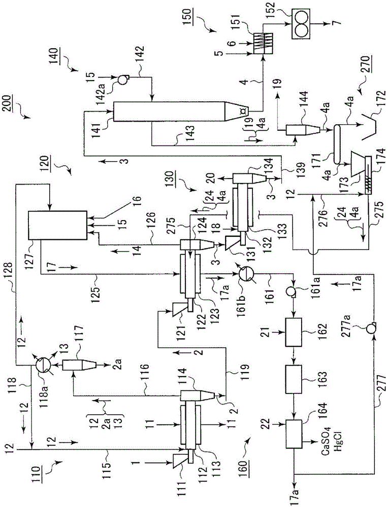
[0089] in accordance with image 3 , 4 A second embodiment of a coal pyrolysis apparatus according to the present invention and an upgraded coal production facility using the coal pyrolysis apparatus will be described. In addition, the same reference numerals as used in the description of the above-described embodiment will be used for the same parts as those of the above-described embodiment, and the description overlapping with the description of the above-described embodiment will be omitted.
[0090] like image 3 As shown, one end side (basal end side) of the pulverized coal feeding pipe 275 is connected to the front end side of the feeding device 174 . A protective gas supply line 276 for supplying an inert gas 12 such as nitrogen is connected to a connection portion between the front end side of the feeding device 174 and the pulverized coal supply pipe 275 . In addition, the gas sending part of the desulfurization device 164 is connected to the outside of the system, and is connected to the middle of the protective gas supply line 276 through a return line 277 including a return blower 277a. The other end side (front end side) of the pulverized coal feed pipe 275 is inserted into the inside of the other end side of the inner cylinder 122 of the coal dry distillation apparatus 120 .
[0091] and, as Figure 4 As shown, the other end (front end) of the pulverized coal feeding pipe 275 is closer to the other end where the temperature drop occurs than the center in the axial direction inside the inner cylinder 122 of the coal dry distillation device 120, that is, A boundary portion B located on the other end side of the portion covered by the outer cylinder 123 and heated with the heating gas 17 and the portion not covered by the outer cylinder 123 and not heated with the heating gas 17 .
[0092] In this embodiment, the pulverized coal conveying device 171, the recovery container 172, the funnel 173, the feeding device 174, the pulverized coal feeding pipe 275, and the protective gas feeding line 276, the return line 276, and the like constitute a pulverized coal supply means, that is, a pulverized coal supply device 270.
[0093]In the upgraded coal production facility 200 according to the present embodiment including such a pulverized coal supply device 270, the production core operation is the same as that in the upgraded coal production facility 100 of the first embodiment described above, so that the low-rank coal 1 can be obtained from the above-mentioned low-rank coal 1. Briquetting coal 7 is made.
[0094] Then, when passing through the return blower 277a of the return line 277, the exhaust gas 17a discharged from the desulfurization device 164 is sent to the shielding gas supply line 276 together with the inert gas 12, and the The feeding device 174 feeds the pulverized coal 4a (particle size: 100 μm or less) in the hopper 173 to one end side (base end side) of the pulverized coal feeding pipe 275, so that the pulverized coal 4a is The amount of coal powder is 1 to 10% by weight (preferably 3 to 5% by weight) of the amount of the dry distillation coal 3 sent from the other end side of the inner cylinder 122 of the coal dry distillation device 120, then the pulverized coal 4a will pass through the shielding gas 24 composed of the exhaust gas 17a and the inert gas 12, and the inside of the pulverized coal feeding pipe 275 will be air-transferred to the other end side (front end side) without passing through the heating gas 17. Heating, ie, supplying to the boundary portion B in the inner cylinder 122 of the coal dry distillation apparatus 120 is performed.
[0095] Since the coal powder 4a supplied to the boundary portion B is not heated in the inner cylinder 122 of the coal dry distillation apparatus 120 in this way, it is much lower than moving from one end side to the other end in the inner cylinder 122. The temperature (about 50° C.) of the carbonized coal 3 (about 350 to 450° C.) that is heated and carbonized on the side is located in the boundary portion B, so compared with the carbonized coal 3 , the carbonized gas 14 contains The mercury-based substances 23 are actively adsorbed on the coal powder 4a.
[0096] Therefore, the pyrolysis coal 3 sent out from the drop port 124 of the coal pyrolysis apparatus 120 can suppress the increase of mercury concentration more than in the case of the above-mentioned embodiment.
[0097] Therefore, according to the present embodiment, the increase in the mercury concentration in the carbonized coal 3 to be produced can be suppressed more than in the case of the above-described embodiment.

Example

[0098] (third embodiment)
[0099] in accordance with Figure 5 A third embodiment of a coal pyrolysis apparatus according to the present invention and an upgraded coal production facility using the coal pyrolysis apparatus will be described. In addition, the same reference numerals as those used in the description of the above-described embodiment will be used for the same parts as those of the above-described embodiment, and the overlapping description with the description of the above-described embodiment will be omitted.
[0100] like Figure 5 As shown, in the middle of the pyrolysis coal transfer line 139, a pyrolysis coal distribution line 371 is connected, and the pyrolysis coal distribution line 371 divides a part of the pyrolysis coal 3 conveyed by the pyrolysis coal conveyance line 139. The pyrolysis coal distribution line 371 is connected to a pyrolysis coal conveying device 372 for conveying the pyrolysis coal 3 divided by the pyrolysis coal distribution line 371 . One side of the pyrolysis coal conveying device 372 ( Figure 5 The middle is the left side) is connected to the middle of the pyrolysis coal transfer line 139 through the pyrolysis coal return line 373 .
[0101] The other side of the pyrolysis coal conveying device 372 ( Figure 5 (center, right) is connected to the funnel 374 that receives the dry distillation coal 3 . The lower part of the said funnel 374 is connected to the base end side of the feeder 375 which feeds the said dry distillation coal 3 in this funnel 374 quantitatively. The front end side of the feeding device 375 is connected to a receiving part of a pulverizing device 376 for refining (particle size: 100 μm or less) the pyrolysis coal 3 . The delivery part of the crushing device 376 is connected to the receiving port of the funnel 173 through a conveyor belt 376 .
[0102] In addition, in this embodiment, the pyrolysis coal distribution line 371 , the pyrolysis coal conveying device 372 , the pyrolysis coal return line 373 , the hopper 374 , the feeding device 375 , and the pulverizing device 376 and the like constitute a pulverized coal production device 370, and the pulverized coal supply device 270 and the pulverized coal production device 370 and the like constitute a pulverized coal supply mechanism.
[0103] In the reformed coal production facility 300 according to the present embodiment in which the pulverized coal supply device 170 and the pulverized coal production device 370 and the like constitute such a pulverized coal supply mechanism, when passing through the reformed coal production facility 100 of the first embodiment described above, The core action is similarly generated, and the briquette coal 7 can be produced from the low-rank coal 1 .
[0104] Furthermore, when the amount of the pulverized coal 2a supplied to the hopper 173 from the cyclone 144 of the inactivation treatment device 140 by the pulverized coal conveying device 171 is insufficient, the dry distillation coal fraction is used The loading line 371 divides a part of the pyrolysis coal 3 conveyed by the pyrolysis coal conveying line 139, and then supplies it to the hopper 374 through the pyrolysis coal conveying device 372, and passes through the feeding device 375 each time. The carbonized coal 3 is finely ground (particle size: 100 μm or less) by quantitative feeding into the pulverizing device 376 , and the coal powder 3 a is supplied to the hopper 173 .
[0105] At this time, when the chars 3 and 3a supplied into the hoppers 173 and 374 are excessive, the pyrolysis coal conveying device 372 is operated in the opposite direction, and the pyrolysis coal conveying line 139 is divided into the pyrolysis coal. The coal 3 is returned to the pyrolysis coal transfer line 139 through the pyrolysis coal return line 373 .
[0106] According to this, even if the amount of the pulverized coal 3a recovered by the cyclone 144 of the inactivation treatment device 140 decreases, the pulverized coal 3a and 4a can always be supplied to the coal in a sufficient amount Inside the inner cylinder 122 of the dry distillation device 120 .
[0107] Therefore, according to the present embodiment, the same effect as in the above-described embodiment can be obtained, and the increase in the mercury concentration in the pyrolysis coal 3 can be suppressed more stably than in the above-described embodiment.

PUM

PropertyMeasurementUnit
Particle size<= 100.0µm

Description & Claims & Application Information

We can also present the details of the Description, Claims and Application information to help users get a comprehensive understanding of the technical details of the patent, such as background art, summary of invention, brief description of drawings, description of embodiments, and other original content. On the other hand, users can also determine the specific scope of protection of the technology through the list of claims; as well as understand the changes in the life cycle of the technology with the presentation of the patent timeline. Login to view more.
Why Eureka
Try Eureka