
Driving device for shaft belt equipment, shaft belt equipment module and power system

A technology for equipment drive and power system, which is applied in the direction of power plant, gas intake of power plant, control device, etc., and can solve problems such as reducing net output power.

Active Publication Date: 2015-04-08
SHENZHEN WISDOM ENERGY TECH CO
View PDF9 Cites 2 Cited by
  • Summary
  • Abstract
  • Description
  • Claims
  • Application Information

AI Technical Summary

Problems solved by technology

Since these shaft devices are also powered by the main shaft of the engine, net power output is reduced

Method used


Image

  • Driving device for shaft belt equipment, shaft belt equipment module and power system
  • Driving device for shaft belt equipment, shaft belt equipment module and power system

Examples


Embodiment Construction

[0016] Before describing the embodiments in detail, it should be understood that the present invention is not limited to the detailed structures or arrangements of elements described herein below or in the accompanying drawings. The present invention can be implemented in other ways. Also, it should be understood that the phraseology and terminology used herein are for descriptive purposes only and should not be interpreted as limiting. The terms "including", "comprising", "having" and similar expressions used herein are meant to include the items listed thereafter, their equivalents and other additional items. In particular, when "a certain element" is described, the present invention does not limit the number of the element to one, but may also include a plurality.

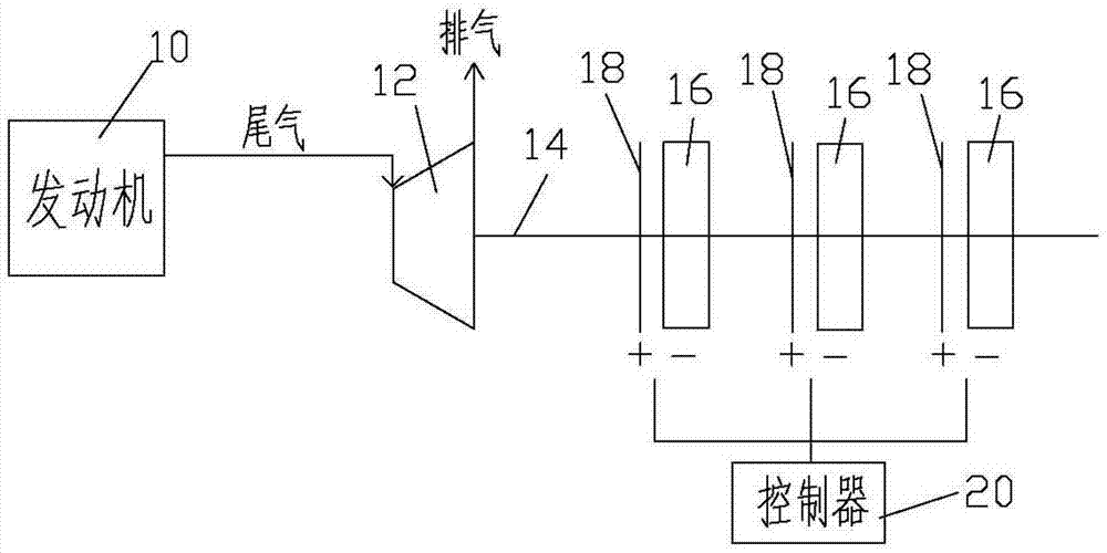
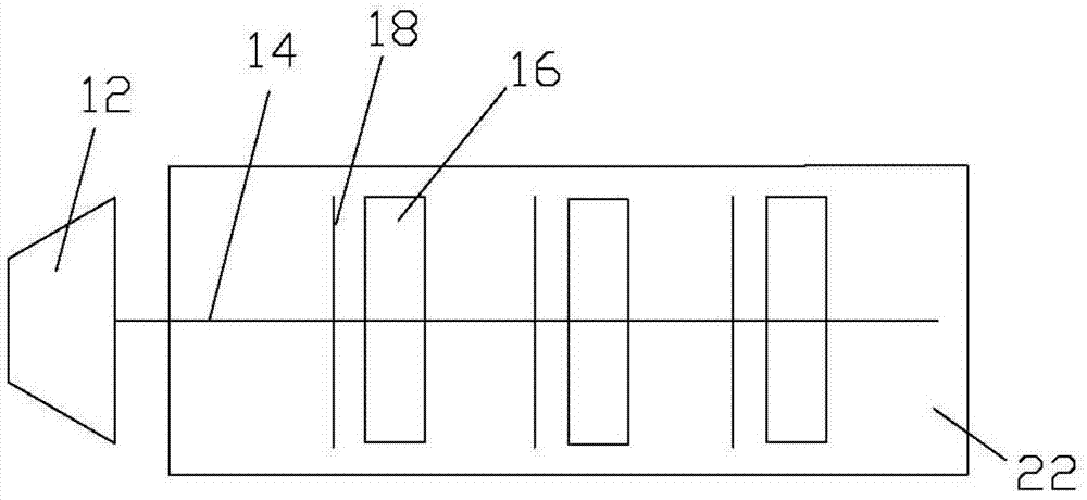
[0017] figure 1 is a simplified system schematic diagram of one embodiment of the powertrain. Such as figure 1 , the power system includes an engine 10 , a turbine 12 , a shaft 14 , at least one shaft device...


PUM


Abstract

The invention provides a driving device for shaft belt equipment. The driving device comprises a turbine, a rotating shaft and at least one connecting structure, wherein the turbine is used for receiving exhausted gas from an engine so as to be driven to rotate by the exhausted gas; the rotating shaft is connected with the turbine so as to be driven to rotate by the turbine; the connecting structure is connected between the rotating shaft and at least one shaft belt equipment. The state of the connecting structure can be converted between engagement and separation; in the state of engagement, the kinetic energy of the rotating shaft in the rotating state can be transmitted to the at least one shaft belt equipment through the connecting structure so as to drive the at least one shaft belt equipment, and while in the state of separation, the rotating shaft stops driving the at least one shaft belt equipment.

Description

technical field [0001] The invention relates to a power system, in particular to a drive device for shaft equipment and a module for shaft equipment of the power system. Background technique [0002] In the driving system of automobiles or other carrying and traction equipment, the main shaft power of the engine not only drives the vehicle, but also drives shaft equipment such as generators, water pumps, oil pumps, air conditioner compressors, brake air compressors, and booster pumps. . Since these shaft devices are also powered by the main shaft of the engine, the net power output is reduced. How to improve the net output power of the engine has always been the relentless pursuit of those skilled in the art. Contents of the invention [0003] In view of this, this paper proposes a shaft drive device to increase the net output power of the engine. [0004] This paper also proposes a shaft equipment module to increase the net output power of the engine. [0005] This pa...

Claims


Application Information

Patent Timeline
Patent Type & Authority Applications(China)
IPC IPC(8): B60K17/28B60K13/04
Inventor 王崎文
Owner SHENZHEN WISDOM ENERGY TECH CO
Learn More