
A fuel cell engine system, its gas supply system and a control method

A technology of engine system and air supply system, which is applied in the direction of fuel cells, fuel cell additives, electrical components, etc., can solve the problems of increasing parasitic load, increasing power consumption, complex control logic, etc., to increase net output power and reduce parasitic Load, compact and simple effect

Active Publication Date: 2021-03-16
WEICHAI POWER CO LTD
View PDF11 Cites 0 Cited by
  • Summary
  • Abstract
  • Description
  • Claims
  • Application Information

AI Technical Summary

Problems solved by technology

[0005] In the patent "A Fuel Cell Hydrogen Circulation Control System and Method" (publication number CN109524690A), it is necessary to add concentration sensors at the hydrogen inlet and outlet, which increases the cost of the fuel cell system. The hydrogen circulation pump is driven by electricity, which increases power consumption , thus increasing the parasitic load, in addition, the control logic of this patent is more complicated and not practical
Only one air compressor is configured in the patent "Fuel Cell and Vehicles Using the Fuel Cell" (CN205621802U). Frequent acceleration and braking of the vehicle during driving will cause the gas in the gas cylinder to fail to meet the compression requirements of the fuel cell stack. Air, which seriously affects the work of the fuel cell
It will also cause the air compressor to start frequently, which will accelerate the decay of the life of the air compressor

Method used


Image

  • A fuel cell engine system, its gas supply system and a control method
  • A fuel cell engine system, its gas supply system and a control method
  • A fuel cell engine system, its gas supply system and a control method

Examples


Embodiment Construction

[0039] The following will clearly and completely describe the technical solutions in the embodiments of the present invention with reference to the accompanying drawings in the embodiments of the present invention. Obviously, the described embodiments are only some, not all, embodiments of the present invention. Based on the embodiments of the present invention, all other embodiments obtained by persons of ordinary skill in the art without making creative efforts belong to the protection scope of the present invention.

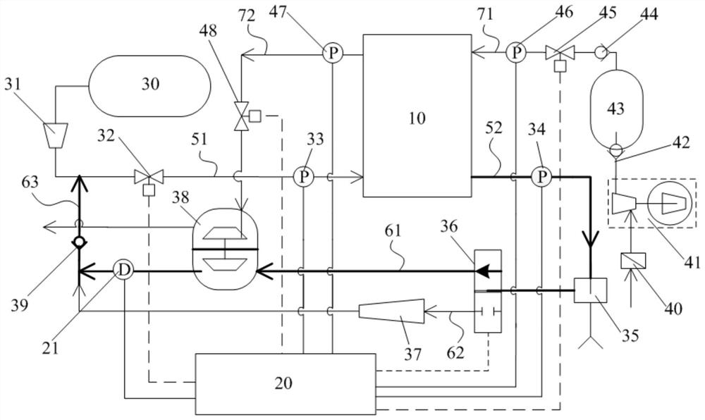
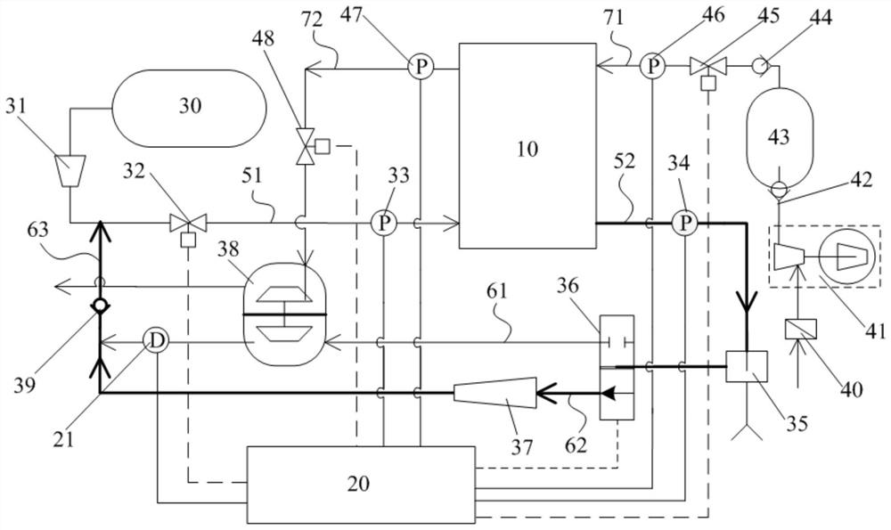
[0040] Please refer to figure 1 and figure 2 , figure 1 It is a schematic diagram of the gas supply system in the specific embodiment of the present invention when the gas expansion and compressor integrated machine is used for hydrogen circulation; figure 2 It is a schematic diagram of the gas supply system in the specific embodiment of the present invention when the hydrogen injector is used for hydrogen circulation. Among them, the thin solid line repres...


PUM


Abstract

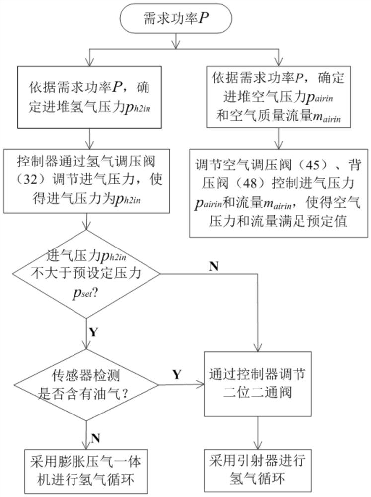
The invention discloses a fuel cell engine system and an air supply system thereof, and a control method. The air supply system comprises a hydrogen supply system and an air supply system; a hydrogenoutlet pipeline is connected with a two-position two-way valve; the two-position two-way valve is connected with a first hydrogen circulating pipeline and a second hydrogen circulating pipeline in parallel; the first hydrogen circulating pipeline is connected to an inlet of a gas compressor of an expansion and gas compression all-in-one machine; and the outlet of the gas compressor is connected toa hydrogen circulation main pipeline, the hydrogen circulation main pipeline is connected to a hydrogen inlet pipeline, a second hydrogen circulation pipeline is connected to the hydrogen circulationmain pipeline through a hydrogen ejector, an inlet hydrogen pressure detection device is arranged on the hydrogen inlet pipeline, and an air outlet pipeline is connected to an expansion machine of the expansion and gas compression all-in-one machine. High-pressure tail gas exhausted by the air supply system is effectively used for driving the expansion and gas compression all-in-one machine to achieve hydrogen cyclic utilization, parasitic loads of the auxiliary system are reduced, and the net output power of the stack is improved.

Description

technical field [0001] The invention relates to the technical field of fuel cell engines, in particular to a fuel cell engine system, its air supply system and a control method. Background technique [0002] A fuel cell power generation system is a complete and stable power generation system consisting of fuel cell modules and necessary auxiliary components, usually referred to as a fuel cell engine system. A stack is a complex with unified electrical output consisting of two or more single cells and other necessary structural components. The fuel cell gas supply system is a system that provides fuel storage, supply and regulation functions for the fuel cell system. [0003] Parasitic load is the power consumed by auxiliary systems (air compressors, hydrogen circulation pumps, water pumps, cooling fans, etc.) to maintain the operation of the fuel cell power generation system. [0004] At present, in the hydrogen supply system, the hydrogen concentration at the inlet and ou...

Claims


Application Information

Patent Timeline
Patent Type & Authority Patents(China)
IPC IPC(8): H01M8/04082H01M8/04089H01M8/0438H01M8/0444
CPCH01M8/04089H01M8/04201H01M8/04388H01M8/0444Y02E60/50
Inventor 任德轩陈文淼王钦普郗富强槐佳张椿陈鹏
Owner WEICHAI POWER CO LTD
Learn More