Device for manually pouring foaming and carbonated beverages

A technology for carbonated beverages and beverages, applied in dispensing devices, valve devices, liquid distribution, etc., can solve the problems of equipment firmness and durability reduction, achieve rapid replacement and maintenance, high reliability and maintainability, and improve durability sexual effect

Active Publication Date: 2016-06-22
谢尔盖·亚历山德罗维奇·布奇克
View PDF9 Cites 4 Cited by
  • Summary
  • Abstract
  • Description
  • Claims
  • Application Information

AI Technical Summary

Problems solved by technology

As far as the device itself is concerned, the robustness and durability of the device with beer stones deposited and formed on its surface is reduced (http: / / www.beermarket.net.ua / forum / viewtopic.php?t=280)

Method used


Image

  • Device for manually pouring foaming and carbonated beverages
  • Device for manually pouring foaming and carbonated beverages
  • Device for manually pouring foaming and carbonated beverages

Examples


Embodiment Construction

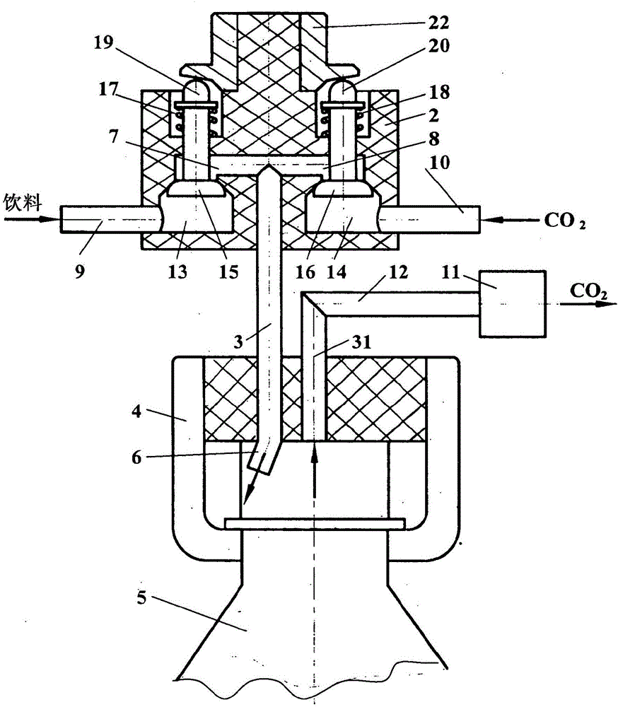
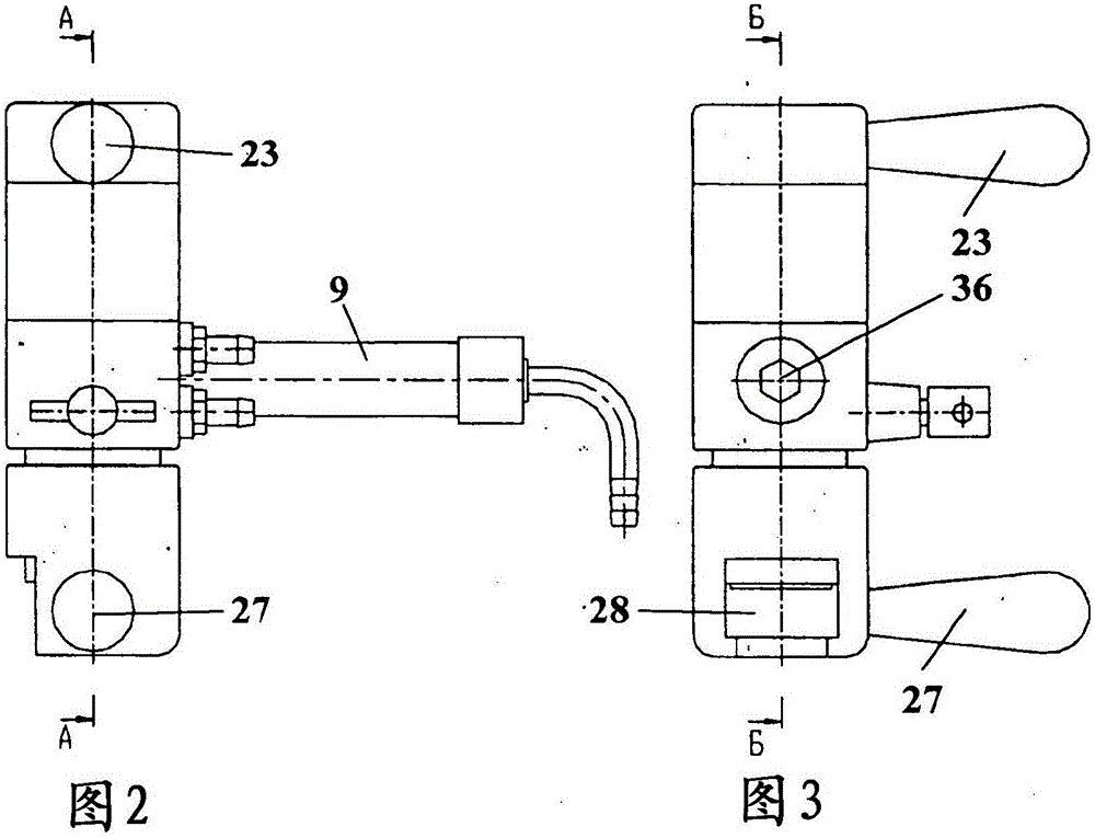
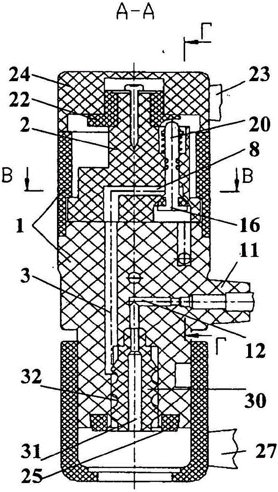
[0029] Devices for manual dispensing of sparkling and carbonated beverages ( Figures 1 to 5 ) comprising: an aggregate housing (aggregatehousing) 1 with a three-way flow switch 2, a discharge channel 3, and a unit 4 for securing the neck of a plastic bottle 5 to the open end 6 of the discharge channel 3 and positioned around the channel 3 . The discharge channel 3 is connected to the beverage supply fitting 9 and the gas supply fitting 10 via intermediate channels 7 and 8 arranged in the flow switch 2 . A control valve 11 is mounted in the housing 1 and connected to the cavity of the container 5 via a channel 12 . A three-way flow switch 2 is located within and removable from the housing 1 , said three-way flow switch being fixed to the housing 1 with a threaded connection.

[0030] The intermediate channels 7 and 8 of the flow switch 2 comprise axially symmetrical chambers 13 and 14 with valve seats and valves 15 and 16 with return springs 17 and 18 mounted in said valve s...


PUM


Abstract

The invention provides a device for manually pouring foaming and carbonated beverages. The invention relates to the food industry, and specifically to commercial equipment, and can be used for dispensing beer and other foaming and carbonated beverages from an isobaric container. The device includes a drainage channel (3) which is connected by means of a three-way flow switching device (2) to tubes for feeding gas and beverage, a node (4) for securing the neck of a plastic bottle (5) to the open end of the drainage channel (3), and a control valve (11) which is connected to the drainage channel (3). The three-way flow switching device (2) contains axially-symmetric cavities (13, 14) with seats, and, installed in the seats, spring-loaded valves (15, 16), the stems (19, 20) of which are kinematically connected to a shaped surface (21) of a rotating element (22). The rotating element (22) is rigidly connected to a control handle (23) for the alternating opening of the valves (15, 16) or for ensuring that the valves (15, 16) are in an initial closed state. The axially-symmetric cavities (13, 14) with seats are connected by means of inner channels (7, 8) to the drainage channel (3) and to the tubes for feeding gas and beverage. The three-way flow switching device (2) is installed in the housing of the device and can be removed therefrom. The axially-symmetric cavities (13, 14) with seats for accommodating the blocking components of the valves (15, 16) are positioned, in the inner channels (7, 8) of the flow switching device (2), transversely relative to the channels (7, 8). Portions of the stems (19, 20) of the valves (15, 16) with springs (17, 18) are positioned, and the rotating element (22) is positioned, in the cavities of the inner channels (7, 8) of the flow switching device (2). The valves (15, 16) with stems (19, 20) and the rotating element (22) which comes into contact with same are made of thermoplastic having an allowable compressive stress of 55-100 MPa, and a surface of the stems (19, 20) of the valves (15, 16) which comes into contact with the shaped surface (21) of the rotating element (22) is developed in the form of a portion of a second-order curve.

Description

technical field [0001] The present invention relates to the food industry, and more particularly to commercial equipment, and to dispensing beer and other sparkling and carbonated beverages from isobaric containers into small containers (mugs) in retail distribution stations, shops, restaurants and bars , glasses) and plastic bottles. Background technique [0002] From US Patent No. 6164083, IPC67D1 / 08, published on December 26, 2000, a beer dispensing device is known comprising: an isobaric container containing beer or several such containers containing various beer brands; Cooling system; dispensing unit, which is equipped with a pipe with a dispensing tap (tap) for pouring the beverage into a small container; and a pipe for delivering beer into the dispensing unit, shaped as a closed circuit and provided with A pump and cooling unit that circulates the drink in the circuit. [0003] Also known is another device for manually pouring sparkling and / or carbonated beverages,...

Claims


Application Information

Patent Timeline
IPC IPC(8): B67D1/04F16K11/00
CPCB67D1/0003B67D1/0082B67D1/08B67D1/12B67D1/04B67D1/14F16K11/00B67C3/06B67C3/242B67C3/28
Inventor 谢尔盖·亚历山德罗维奇·布奇克
Owner 谢尔盖·亚历山德罗维奇·布奇克
Why Eureka
Try Eureka