Rotatable type lifting device

A rotary, spreader technology, used in transportation and packaging, load hanging components, etc., can solve problems such as safety accidents, landings, and slings, and achieve the effect of enhancing stability and safety.

Inactive Publication Date: 2015-04-08
张雪燕
View PDF5 Cites 0 Cited by
  • Summary
  • Abstract
  • Description
  • Claims
  • Application Information

AI Technical Summary

Problems solved by technology

[0003] The existing spreader has some structural defects, especially in windy weather. Once the wind blows, the spreader will be blown to this side or even under the negative pressure of the wind. Forced to land due to increased resistance, and sometimes safety accidents can occur

Method used


Image

  • Rotatable type lifting device
  • Rotatable type lifting device
  • Rotatable type lifting device

Examples


Embodiment Construction

[0014] The present invention is described in further detail now in conjunction with accompanying drawing. These drawings are all simplified schematic diagrams, which only illustrate the basic structure of the present invention in a schematic manner, so they only show the configurations related to the present invention.

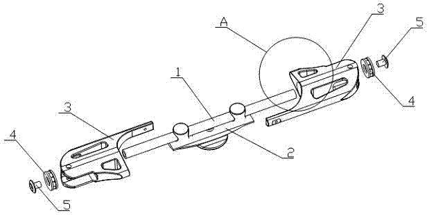
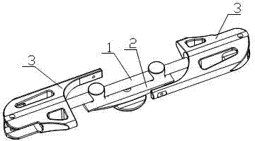
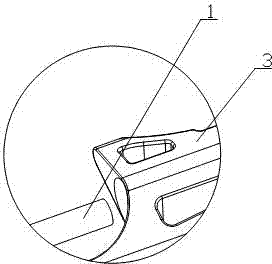
[0015] Such as figure 1 , figure 2 and image 3 The rotatable lifting device shown includes a beam 1, a suction cup type suspension ring 2 is installed at the center of the beam 1, and two sheaths 3 are respectively installed on the left and right sides of the beam 1, and the two sheaths 3 pass through Fastening bolt 5 is equipped with bearing 4, and rotating motor output shaft is installed on the bearing 4, and crossbeam 1 rotates under the effect of rotating motor.

[0016] The two sheaths 3 installed on the left and right sides of the beam 1 are distributed along the length direction of the beam 1 as mirror images. The two sheaths 3 installed on the le...


PUM


Abstract

The invention relates to the technical field of lifting devices, and particularly relates to a rotatable type lifting device. The rotatable type lifting device comprises a cross beam, wherein a suction disc type lifting ring is arranged at the central position of the cross beam, the left side and the right side of the cross beam are respectively provided with two protective sleeves, and the cross beam does rotational motion under the action of a rotary motor. The rotatable type lifting device disclosed by the invention can enable a lifting tool to follow to do the rotational motion by virtue of the action of the rotary motor when encountering windy weather, so that the wind resistance is counteracted.

Description

technical field [0001] The invention relates to the technical field of sling devices, in particular to a rotatable sling device. Background technique [0002] The spreader refers to the device for lifting heavy objects in the hoisting machinery. The most commonly used spreader for lifting finished items is the hook, and others include lifting rings, lifting suction cups, clamps and forks. It is widely used in the lifting industry. [0003] The existing spreader has some structural defects, especially in windy weather. Once the wind blows, the spreader will be blown to this side or even under the negative pressure of the wind. The resistance increases and is forced to land, and sometimes safety accidents can occur. Contents of the invention [0004] The technical problem to be solved by the present invention is: In order to solve the problems raised in the background technology above, the present invention provides a rotatable sling device, which can make the sling Fol...

Claims


Application Information

Patent Timeline
Patent Type & Authority Applications(China)
IPC IPC(8): B66C1/10
CPCB66C1/10
Inventor 张雪燕
Owner 张雪燕
Why Eureka
Try Eureka