Hydraulic Chassis Drive System of Multifunctional Agricultural Locomotive

A driving system and multi-functional technology, applied in the direction of fluid pressure actuators, mechanical equipment, servo motors, etc., can solve the problems of large impact load, single driving form, difficulty in meeting the needs of normal driving of agricultural vehicles, etc., to achieve multiple functions , to meet the effect of normal driving needs

Active Publication Date: 2017-01-04
宁波中意液压马达有限公司
View PDF8 Cites 0 Cited by
  • Summary
  • Abstract
  • Description
  • Claims
  • Application Information

AI Technical Summary

Problems solved by technology

The chassis of agricultural locomotives is usually a mechanical drive structure, and the common defects of mechanically driven chassis are: first, due to the use of multi-stage gear shifting and shifting mechanism transmission, the chassis of the transmission system will be relatively heavy, and the braking system It will also be more complicated, the structural layout is more difficult, and the operation is inconvenient; second, the impact load is relatively large during shifting, starting, and acceleration.
For this reason, there are currently hydraulically driven chassis on the market. However, the existing hydraulic chassis drive systems have the defect of a relatively single driving form, which makes it difficult to meet the needs of agricultural vehicles for normal driving in various road conditions.

Method used


Image

  • Hydraulic Chassis Drive System of Multifunctional Agricultural Locomotive

Examples


Embodiment Construction

[0026] The present invention will be further described below in conjunction with the accompanying drawings.

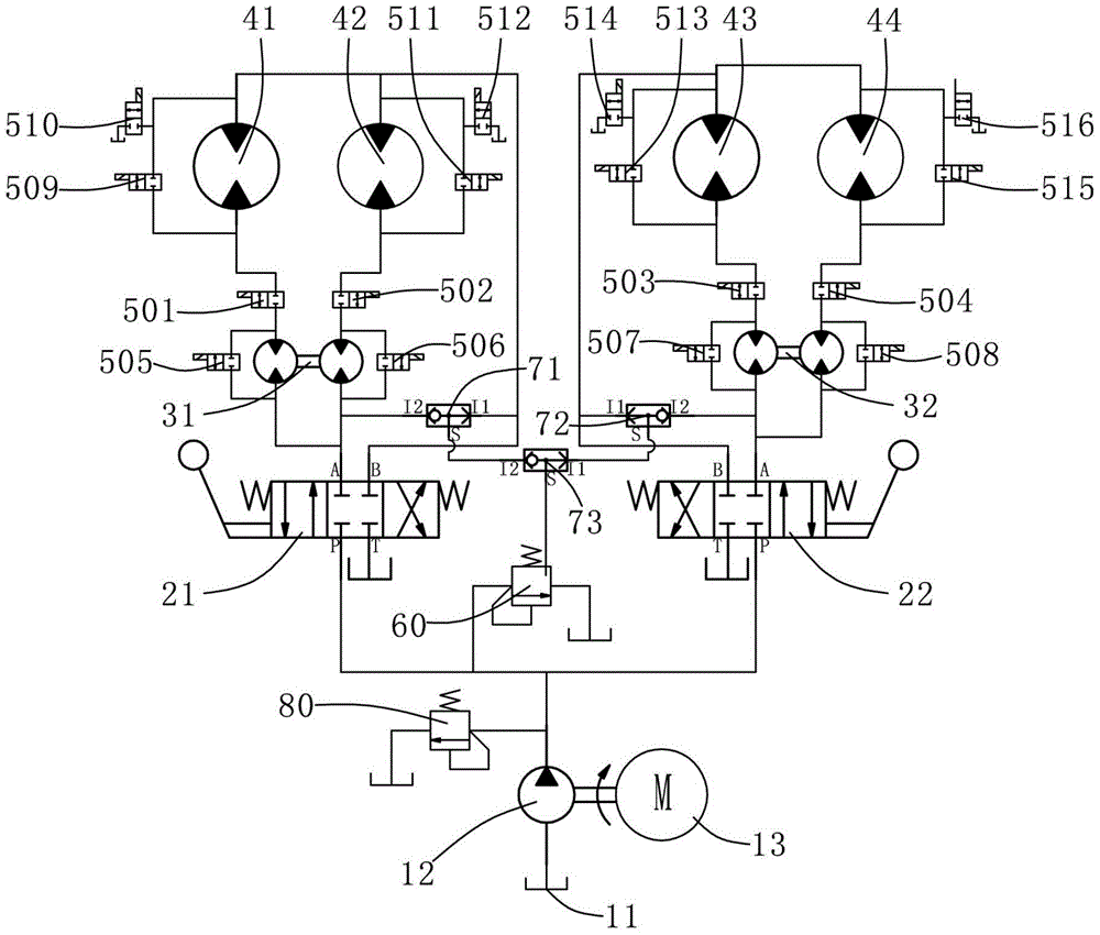
[0027] Such as figure 1The hydraulic chassis drive system of the multifunctional agricultural locomotive shown includes power components, main control mechanism, auxiliary control mechanism, flow distribution mechanism and executive mechanism. The power assembly includes a fuel tank 11 , a gear pump 12 and an engine 13 that drives the gear pump 12 to work. The oil inlet end of the gear pump 12 is connected to the fuel tank 11 .

[0028] The main control mechanism includes the first manual three-position four-way valve 21 and the second manual three-position four-way valve 22, the oil supply P port of the first manual three-position four-way valve 21, the second manual three-position four-way valve 22 The oil supply P port of the gear pump 12 is connected with the oil outlet port of the gear pump 12, and the oil return T port of the first manual three-position four-way...


PUM


Abstract

The invention discloses a hydraulic chassis driving system of a multifunctional agricultural locomotive. The hydraulic chassis driving system comprises a power assembly, a main control mechanism, an assistant control mechanism, a flow distributing mechanism and an executing mechanism, wherein the power assembly comprises a fuel tank, a gear pump and an engine; a fuel inlet end of the gear pump is connected with the fuel tank; the main control mechanism comprises a first manual three-position four-way valve and a second manual three-position four-way valve; fuel feeding ports P of the first manual three-position four-way valve and the second manual three-position four-way valve are connected with a fuel outlet end of the gear pump; fuel returning ports T of the first manual three-position four-way valve and the second manual three-position four-way valve are connected with the fuel tank respectively; the flow distributing mechanism comprises a first synchronous flow-dividing motor and a second synchronous flow-dividing motor; the executing mechanism comprises a first driving motor, a second driving motor, a third driving motor and a fourth driving motor. The hydraulic chassis driving system is simple and reasonable in structure, convenient to manipulate and diverse in functions, and can meet normal running demands of an agricultural vehicle under various road conditions.

Description

technical field [0001] The invention relates to the technical field of chassis drive systems, in particular to a hydraulic chassis drive system for a multifunctional agricultural locomotive. Background technique [0002] With the development of social science and technology, many jobs in agriculture have been replaced by machinery, which greatly improves people's work efficiency and reduces people's labor intensity. Since agricultural locomotives have been driving on poor roads for a long time, in order to ensure the normal running of the locomotives, the chassis drive design requirements for agricultural locomotives are extremely strict. The chassis of agricultural locomotives is usually a mechanical drive structure, and the common defects of mechanically driven chassis are: first, due to the use of multi-stage gear shifting and shifting mechanism transmission, the chassis of the transmission system will be relatively heavy, and the braking system It will also be more comp...

Claims


Application Information

Patent Timeline
Patent Type & Authority Patents(China)
IPC IPC(8): F15B11/16F15B13/02
CPCF15B11/16F15B13/06
Inventor 洪庚建路小江周春华
Owner 宁波中意液压马达有限公司
Why Eureka
Try Eureka