Casting defect ray detection system

A technology for ray detection and casting defects, which is applied in the field of detection equipment, can solve problems such as heavy workload, low work efficiency, and affecting the detection time of castings, reduce the limitation of manual proficiency, save the time of manual adjustment, and improve The effect of the overall detection time

Inactive Publication Date: 2015-04-08
CHONGQING UNIV OF TECH
View PDF6 Cites 5 Cited by
  • Summary
  • Abstract
  • Description
  • Claims
  • Application Information

AI Technical Summary

Problems solved by technology

The workpiece is manually placed on the detection turntable. The detection process is manually detected. After the detection, whether the workpiece is qualified or not needs to be manually classified. The workload is heavy and the work efficiency is also very low. Due to the different detection positions, X-rays need to be replaced many times. The strength, repeated adjustments also affect the detection time of castings, and the detection time is closely related to the detection proficiency of the operator

Method used


Image

  • Casting defect ray detection system
  • Casting defect ray detection system
  • Casting defect ray detection system

Examples


Embodiment Construction

[0038] In describing the present invention, it should be understood that the terms "longitudinal", "transverse", "length", "width", "upper", "lower", "vertical", "horizontal", "top", The orientation or positional relationship indicated by "bottom", "inner", "outer", etc. is based on the orientation or positional relationship shown in the drawings, and is only for the convenience of describing the present invention and simplifying the description, rather than indicating or implying No device or element must have a specific orientation, be constructed, and operate in a specific orientation and therefore should not be construed as limiting the invention.

[0039] In addition, the terms "first" and "second" are used for descriptive purposes only, and cannot be interpreted as indicating or implying relative importance or implicitly specifying the quantity of indicated technical features. Thus, a feature defined as "first" and "second" may explicitly or implicitly include one or mor...


PUM


Abstract

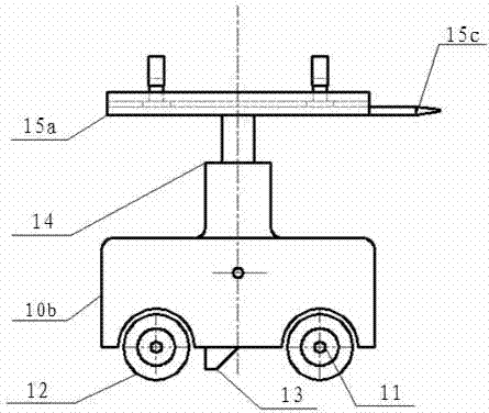
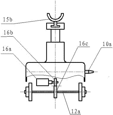
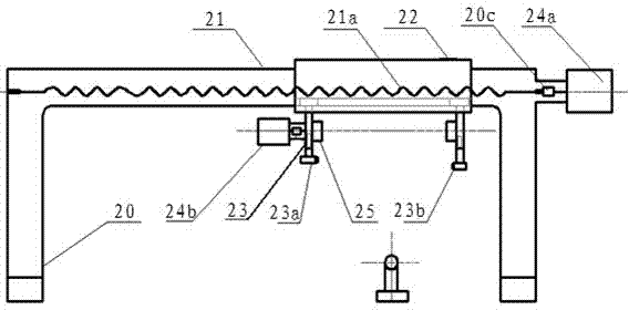
The invention relates to a casting defect ray detection system which comprises a PLC, a casting transport vehicle, a detection chamber, an X-ray generator and a detection device, wherein the casting transport vehicle is used for transporting a casting into the detection chamber, the X-ray generator and the detection device are arranged in the detection chamber, the detection device comprises a detection platform body, a detection guide rail, a detection platform, a casting clamp and a casting drive structure, the casting transported by the casting transport vehicle is mounted on the detection platform by virtue of a casting clamp, the casting drive structure is used for driving the casting to transversely move and rotate, the X-ray generator generates X rays to realize detection of the casting, and the PLC is used for controlling the casting transport vehicle, the detection chamber, the X-ray generator and the detection device. According to the casting defect ray detection system, transportation, transmission and rotation of the casting are all controlled by adopting the PLC with PLC bus control as a center, and axial and radial detection of the casting is realized by virtue of the casting drive structure, so that the manual regulation time is saved, and the integral detection time of the casting is greatly increased.

Description

technical field [0001] The invention relates to detection equipment, in particular to a casting defect ray detection system. Background technique [0002] Soon after Mr. Roentgen discovered X-rays, he realized that X-rays could be used for material inspection. But it wasn't until the 1970s that X-rays began to be used in industry. In the process of X-ray inspection, fan-shaped X-rays pass through the sample to be inspected, and then form an enlarged X-ray image on the image receiver (mostly use X-ray image intensifiers now). The focal area and object distance of x-ray determine the size of the imaging area. Increasing the object distance can increase the imaging area. However, since x-ray is a surface light source, increasing the object distance will also make the image blur. Therefore, the clarity of the image limits the area of ​​X-ray imaging, which directly results in the necessity of multi-station shooting of large castings in order to complete the inspection of its i...

Claims


Application Information

Patent Timeline
Patent Type & Authority Applications(China)
IPC IPC(8): G01N23/083
Inventor 余永维杜柳青程功利
Owner CHONGQING UNIV OF TECH
Why Eureka
Try Eureka