
Small integrated two-dimensional opto-acoustic galvanometer excitation source

An excitation source, small technology, applied in the direction of material analysis, measuring device, instrument, etc. by optical means, can solve the problems of large mechanical vibration, time-consuming, complicated operation, etc., achieve good dynamic response characteristics, improve detection time, improve The effect of scanning accuracy

Inactive Publication Date: 2012-08-01
曾吕明 +2
View PDF6 Cites 5 Cited by
  • Summary
  • Abstract
  • Description
  • Claims
  • Application Information

AI Technical Summary

Problems solved by technology

Due to the advantages of micro-focus energy and nanosecond pulse width, solid-state lasers are currently the common excitation source for photoacoustic technology, but many disadvantages such as large size, high price, and difficult maintenance have hindered the market promotion of photoacoustic technology.
[0004] For example, in 2006, Allen et al. reported that an array of four pulsed laser diodes was used as a photoacoustic excitation source to realize large-area two-dimensional photoacoustic imaging (T. J. Allen, and P. C. Beard, “Pulsed near-infrared laser diode excitation system for biomedical photoacoustic imaging," Opt. Lett. 31(23), 3462-3464, 2006); in 2008, Maslov et al. reported that using a single amplitude-modulated continuous laser diode as a photoacoustic excitation source also realized large-area photoacoustic scanning imaging (K. Maslov and L. V. Wang, “Photoacoustic imaging of biological tissue with intensity-modulated continuous-wave laser,” J. Biomed. Opt. 13(2), 024006, 2008); due to the low peak power of semiconductor lasers, generally Under the circumstances, it does not exceed 200W, so the above method requires the sensor to be driven by a stepping motor to perform circular or linear mechanical scanning to receive photoacoustic signals in different directions, which has many shortcomings such as time-consuming, complicated operation, and large mechanical vibration. Considerable limitations, unable to meet the actual needs of high precision, high stability and fast imaging

Method used


Image

  • Small integrated two-dimensional opto-acoustic galvanometer excitation source

Examples


Embodiment 1

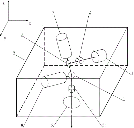
[0017] Embodiment 1 The structure of this embodiment is as follows figure 1 As shown, the names of each component are: 1. Light source, 2. Computer, 3. Acquisition circuit, 4. Preprocessing circuit, 5. Driving circuit, 6. Ultrasonic array sensor, 7. Collimating lens group, 8. X axis Reflective galvanometer, 9. Y-axis reflective galvanometer, 10. Focusing lens group, 11. X-axis motor, 12. Y-axis motor.

[0018] Among them, the light source 1 is a pulsed semiconductor laser diode (PGAS1S24, Hoffo), the working wavelength is 905nm, the peak power is 49W, the pulse width is 150ns, and the single pulse energy is about 7.3uJ; the X-axis and Y-axis motors use precision servo motors, repeat The accuracy can reach 8μrad.

[0019] This example includes laser diode, collimating lens group, X-axis reflective galvanometer, Y-axis reflective galvanometer, focusing lens group, protective mirror, X-axis motor, Y-axis motor, housing; X-axis reflective galvanometer and X-axis motor mechanical ...


PUM


Abstract

The invention provides a small integrated two-dimensional opto-acoustic galvanometer excitation source, which is formed by a laser diode, a collimating lens group, an X-axis reflecting galvanometer, a Y-axis reflecting galvanometer, a focusing lens group, a protective lens, an X-axis motor, a Y-axis motor and a casing and can achieve large-area, high-speed and high-stability small opto-acoustic excitation scanning. The small integrated two-dimensional opto-acoustic galvanometer excitation source applies fast and efficient two-dimensional laser galvanometer scanning technology to the field of opto-acoustic excitation, is integrally designed with the small-volume laser diode, and achieves small excitation of large-area opto-acoustic imaging.

Description

technical field [0001] The invention relates to a photoacoustic excitation technology, in particular to a small and integrated two-dimensional photoacoustic vibrating mirror excitation source. Background technique [0002] The laser galvanometer is a high-precision, high-speed servo control system composed of a driver board and a high-speed swing motor, which can easily realize two-dimensional deflection of the laser beam. It has the advantages of small size, fast response, high scanning speed, and large scanning range. And other advantages, currently widely used in laser marking, laser cutting, laser drilling and other fields. [0003] Photoacoustic technology is a newly developed non-invasive nondestructive testing technology based on the difference in optical absorption inside biological tissues and using ultrasound as the medium. Solid-state lasers are currently the common excitation source for photoacoustic technology due to their advantages of micro-focus energy and ...

Claims


Application Information

Patent Timeline
IPC IPC(8): G01N21/17
Inventor 曾吕明纪轩荣杨迪武
Owner 曾吕明
Learn More