A switch using a torsion spring as a terminal

A technology of torsion springs and terminals, which is applied in the field of electronic switches, can solve the problems affecting the feel and life of keys, and the insufficient strength of metal sheets, etc., and achieve the effects of good application prospects, good feel, and simple structure

Active Publication Date: 2017-11-28
HUIZHOU TRANTEK ELECTRONICS
View PDF7 Cites 2 Cited by
  • Summary
  • Abstract
  • Description
  • Claims
  • Application Information

AI Technical Summary

Problems solved by technology

Existing key switches use moving contacts made of metal sheets. Due to the limitation of the internal space of the switch, the strength of the metal sheets is relatively insufficient, which affects the feel and life of the keys.

Method used


Image

  • A switch using a torsion spring as a terminal
  • A switch using a torsion spring as a terminal
  • A switch using a torsion spring as a terminal

Examples


Embodiment 1

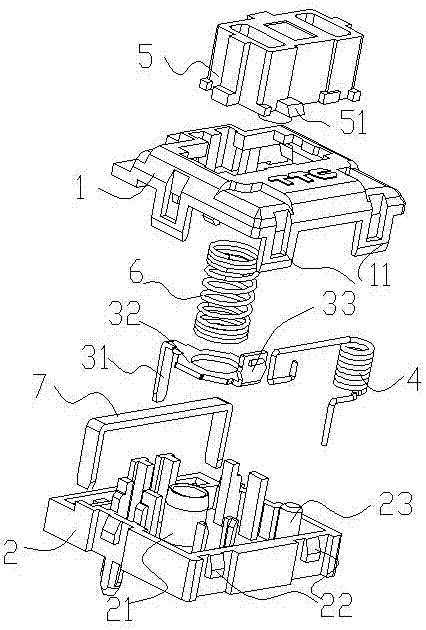
[0027] figure 1 It is the overall structure explosion diagram of embodiment 1, such as figure 1 As shown, the switch using a torsion spring as a terminal according to the present invention includes an upper cover 1, a base 2, a pressing member 5, a return spring 6, a movable terminal 4 and a fixed terminal 3, and a plurality of buttonholes are arranged on the periphery of the upper cover 1 11, and the place where the base 2 corresponds to the button hole 11 of the upper cover 1 is provided with a card position 22, and the upper cover 1 and the base 2 can be fastened through the cooperation of the button hole 11 and the card position 22. After the buckle, the upper cover 1 and the A cavity is formed in the middle of the base 2 for placing the pressing member 5 , the return spring 6 , the movable terminal 4 and the fixed terminal 3 . The base 2 is provided with a guide post 21 , the lower part of the guide post 21 extends out of the bottom of the base 2 , the return spring 6 is...

Embodiment 2

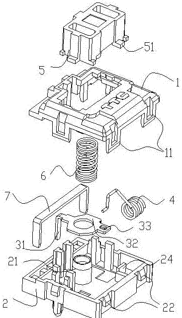
[0032] Figure 4 It is the overall structure explosion diagram of embodiment 2, as Figure 4 As shown, embodiment 2 is the same as embodiment 1, including upper cover 1, base 2, pressing member 5, return spring 6, movable terminal 4 and fixed terminal 3, and the left and right ends of the upper cover 1 are respectively provided with a button hole 11. At the same time, there are two button holes 11 in the lower part, and the base 2 is provided with a card position 22 corresponding to the button holes 11 of the upper cover 1. The upper cover 1 and the base 2 can cooperate with the button holes 11 and the card positions 22. After fastening, a cavity is formed between the upper cover 1 and the base 2 for placing the pressing member 5 , the return spring 6 , the movable terminal 4 and the fixed terminal 3 . The base 2 is provided with a guide post 21, one end of the guide post 21 is fixed on the base 2, and the other end is connected and fixed to the lower part of the pressing mem...

Embodiment 3

[0037] Figure 7 It is the overall structure explosion diagram of embodiment 3, as Figure 7 As shown, the embodiment 3 is the same as the embodiment 2, including the upper cover 1, the base 2, the pressing member 5, the return spring 6, the movable terminal 4 and the fixed terminal 3, and the left and right ends of the upper cover 1 are respectively provided with a button hole 11. At the same time, there are two button holes 11 in the lower part, and the base 2 is provided with a card position 22 corresponding to the button holes 11 of the upper cover 1. The upper cover 1 and the base 2 can cooperate with the button holes 11 and the card positions 22. After fastening, a cavity is formed between the upper cover 1 and the base 2 for placing the pressing member 5 , the return spring 6 , the movable terminal 4 and the fixed terminal 3 . The base 2 is provided with a guide post 21, one end of the guide post 21 is fixed on the base 2, the other end is connected and fixed with the ...


PUM


Abstract

The invention discloses a switch using a torsional spring as a terminal. The switch comprises an upper cover, a base, a fixed terminal, a movable terminal and a pressing piece, wherein the base is provided with a guide post; the pressing piece is connected to the guide post sleeved with a return spring; the upper end of the pressing piece protrudes out of the upper cover for pressing; the upper cover is buckled with the base, so that a cavity is formed between the upper cover and the base; the fixed terminal and the movable terminal are arranged in the cavity; one end of the fixed terminal and one end of the movable terminal penetrate through base and are connected with an external circuit; the movable terminal is the torsional spring and is mounted on the end, adjacent to the fixed terminal, of the base; one end of the torsional spring penetrates out of the base for line connection and is fixed to the base; and the other end of the torsional spring serves as an action arm controlled by the pressing piece to contact with the fixed terminal. Compared with the prior art, the torsional spring having good elasticity is adopted as the movable terminal, so that the switch using the torsional spring as the terminal can provide better operation experience. Besides, the torsional spring is comparatively low in manufacturing cost. The switch is simple in structure and long in service lifetime. .

Description

technical field [0001] The invention relates to an electronic switch, in particular to a switch using a torsion spring as a terminal. Background technique [0002] Many operations of existing devices require the use of key switches as input means. The quality of the key switch determines the experience of the input device, and it is necessary to ensure a good feel and service life. The existing key switch adopts the movable contact piece made of metal sheet. Due to the limitation of the internal space of the switch, the strength of the metal sheet is relatively insufficient, which affects the feel and life of the key. Contents of the invention [0003] In view of this, the problem to be solved by the present invention is to provide a switch using a torsion spring as a terminal with good hand feeling, long service life, simple structure and low manufacturing cost. [0004] In order to solve the above problems, the present invention adopts the following technical solutions:...

Claims


Application Information

Patent Timeline
Patent Type & Authority Patents(China)
IPC IPC(8): H01H13/12
CPCH01H13/30H01H2205/034
Inventor 余正明
Owner HUIZHOU TRANTEK ELECTRONICS
Why Eureka
Try Eureka