Connector and realization method of connector

A connector and electrical connection technology, which is applied to the parts, connections, and two-part connection devices of the connection device, etc., can solve the problems of poor convenience and low flexibility, and achieve the effect of reducing the number and succinct appearance

Active Publication Date: 2015-04-08
GOERTEK INC
View PDF7 Cites 8 Cited by
  • Summary
  • Abstract
  • Description
  • Claims
  • Application Information

AI Technical Summary

Problems solved by technology

[0003] The present invention provides a connector and a method for realizing the connector to solve the problems of low flexibility and poor convenience in the prior art because the power plug needs to work with the power socket in a specific direction or angle

Method used


Image

  • Connector and realization method of connector
  • Connector and realization method of connector
  • Connector and realization method of connector

Examples


Embodiment Construction

[0034] In order to make the object, technical solution and advantages of the present invention clearer, the implementation manner of the present invention will be further described in detail below in conjunction with the accompanying drawings.

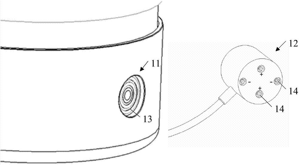
[0035] figure 1 A schematic diagram of a connector provided by an embodiment of the present invention. The connector includes a power socket 11 and a power plug 12 that matches the power socket 11. The electrodes of the power socket 11 are annular or circular pole pieces 13, and the power plug 12 is corresponding to the circular or circular pole piece 13 of the power socket 11. One or more pairs of positive and negative terminals 14 are arranged at the position, and the corresponding position is the position on the power plug that is in contact with the pole pieces after the power plug is inserted into the power socket; when the power plug 12 is inserted into the power supply in any direction or angle When the socket 11 is used, the p...


PUM


Abstract

The invention discloses a connector and a realization method of the connector. The connector comprises a power socket and a power plug which is matched with the power socket. Annular or circular electrode sheets are arranged on the power socket, and a pair or multiple pairs of positive and negative electrode terminals are arranged at the corresponding positions of the power plug so that the positive and negative electrode terminals can be contacted with the annular or circular electrode sheets when the power plug is inserted into the power socket in any directions or angles, and thus electrical connection of the power plug and the power socket is realized. Besides, in a preferable embodiment, an earphone jack is arranged at the central position of the power socket, and the connector is enabled to have functions of the earphone jack and the power socket simultaneously so that space of equipment is effectively utilized, the number of external interfaces of the equipment is reduced and appearance of the equipment is enabled to be more concise.

Description

technical field [0001] The invention relates to the field of electronic technology, in particular to a connector and a method for realizing the connector. Background technique [0002] When the existing power plug and other connectors are connected to the terminal body, the power plug must be inserted into the power socket of the terminal body at a specific angle. If it is inserted from other angles, there will be a problem that the power plug cannot be inserted into the power socket, thus As a result, the flexibility and convenience of the power plug are poor, which brings inconvenience to users. For example, when the light is dark or the placement of the terminal prevents the user from seeing the power socket clearly, there is often a problem that the power plug cannot be inserted into the power socket, and the user frequently plugs and unplugs the power plug, which is easy to cause power failure on the terminal body. Scratches or wear on sockets and power plugs reduce th...

Claims


Application Information

Patent Timeline
Patent Type & Authority Applications(China)
IPC IPC(8): H01R24/38H01R13/04
CPCH01R13/04H01R13/10H01R24/28H01R24/58H01R24/76H01R27/00H01R24/38H01R13/6205H01R43/20H01R39/10
Inventor 刘崧徐诚信
Owner GOERTEK INC
Why Eureka
Try Eureka