Compression joint branched bus bar and branched compression joint method thereof

A technology of busbars and branches, which is applied in the direction of connection and connection completed by deformation, installation of busbars, and connection where permanent deformation plays a role, and can solve problems such as virtual welding, high current heating, busbar deformation, etc.

Active Publication Date: 2012-12-26
镇江西门子母线有限公司
View PDF5 Cites 6 Cited by
  • Summary
  • Abstract
  • Description
  • Claims
  • Application Information

AI Technical Summary

Problems solved by technology

Among them, the disadvantage of welding is that it is easy to deform the busbar, and the second is that the starting part of the welding often has a virtual weld due to the temperature not meeting the requirements, which affects the quality of the electrical connection
[0004] However, practice has shown that this crimping structure is more suitable for the connection between the busbar and the busbar close to the power supply terminal, and when this structure is also used between the busbar of the main line and the busbar of the branch line, because the electrical connection realized by the pure mechanical structure has A certain contact resistance, especially when the deformed material that is squeezed out is filled into the tooth valley of the sawtooth edge, there will inevitably be a certain micro-gap, so it is easy to generate heat and cause loss when transmitting a large current

Method used


Image

  • Compression joint branched bus bar and branched compression joint method thereof
  • Compression joint branched bus bar and branched compression joint method thereof
  • Compression joint branched bus bar and branched compression joint method thereof

Examples


Embodiment 1

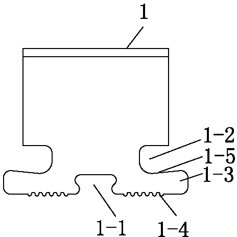
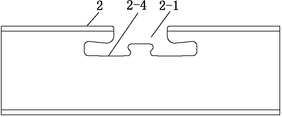
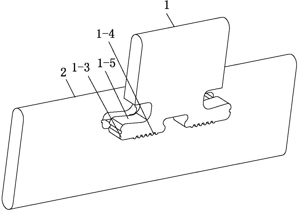
[0019] The crimping branch busbar of this embodiment is as follows: Figure 1 to Figure 4 As shown, it includes the main line busbar 2 and the branch line busbar 1. The middle part of the end of the connection end of the branch line busbar 1 and the main line busbar 2 has a first depression 1-1, and there are symmetrical depressions 1-2 on both sides of the end, forming a Crimp ends for symmetrical side extension legs 1-3. One side of the branch of the main line busbar 2 is formed with a recess 2-1 matching the shape of the symmetrical side extension leg 1-3. The side protruding foot 1-3 corresponds to the side of the terminal of the branch line busbar connection end to form a sawtooth edge 1-4 embedded in the notch 2-1 corresponding to the side 2-4 when crimping is formed. After the main line busbar 2 is crimped with the branch line busbar 1, a tapered slit hole 1-6 is formed in the middle of the side 1-5 opposite the side extension foot 1-3 and the serrated edge 1-4. The sl...


PUM


Abstract

The invention relates to an improvement on a bus bar branched compression joint structure, and relates to a compression joint method thereof simultaneously, belonging to the technical field of electric connecting facilities. A compression joint branched bus bar comprises a main line bus bar and a branched line bus bar; the middle part of the tip of a connecting end between the branched line bus bar and the main line bus bar is provided with a first recess; both sides of the tip are provided with symmetrical recesses, so that a compression joint end with symmetrical lateral extension feet is formed; one side of a branched part of the main line bus bar is provided with concave gaps which are matched with the shapes of the symmetrical lateral extension feet; sawtooth sides embedded into corresponding sides of the concave gaps during compression joint are formed on one sides of the lateral extension feet, which correspond to the tip of the connecting end of the branched line bus bar; after the main line bus bar is in compression joint with the branched line bus bar, at least one roulette is formed in one side of each lateral extension foot, which is opposite to each sawtooth side; and a roulette pin is wedged into each perforation hole. The improvement disclosed by the invention is reasonable and skillful, convenience is brought to implementation, deformation and cold solder joints caused by welding can be avoided, and micro-gaps possibly existing in tooth valleys can be closed through the compression action of the roulette pin on the sawtooth side, so that the contact resistance is reduced effectively.

Description

technical field [0001] The invention relates to a crimping branch busbar, in particular to an improvement of a busbar branch crimping structure, and at the same time, the invention also relates to its crimping method, which belongs to the technical field of electrical connection facilities. Background technique [0002] The bus bar is a commonly used electrical connector for various high-voltage equipment such as switch cabinets. It is often required to be tapped vertically by the bus bar in T-shaped vertical branches, vertical elbows, sockets and other parts. According to the applicant's understanding, there are two ways of tapping the existing busbars, namely welding and crimping. Among them, the disadvantage of welding is that it is easy to deform the busbar, and the second is that there is often a virtual weld at the starting part of the welding because the temperature has not yet reached the requirement, which affects the quality of the electrical connection. The exist...

Claims


Application Information

Patent Timeline
Patent Type & Authority Applications(China)
IPC IPC(8): H01R4/18H01R43/04H02G5/00
Inventor 祝敏王宁马翔
Owner 镇江西门子母线有限公司
Why Eureka
Try Eureka