

Communication method, base station and user equipment
A technology of user equipment and communication methods, applied in wireless communication, signaling distribution, channel coding adjustment, etc., to achieve the effect of increasing overhead and improving frequency efficiency
- Summary
- Abstract
- Description
- Claims
- Application Information
AI Technical Summary
Problems solved by technology
Method used
Image

Examples
no. 1 example
[0043] The first embodiment of the present disclosure provides a communication method for constructing a parameter table in a wireless communication system including an eNode B and a UE. The communication method includes the steps of: defining a parameter table in both the eNode B and the UE, the parameter table including all entries of a conventional parameter table and extended entries; and sending from the eNode B to the UE a bitmap indication representing a sub-table selected from the parameter table, wherein the number of entries in the sub-table is the same as the number of entries in the legacy parameter table.
[0044] Before describing in detail the implementation of the communication method according to the first embodiment of the present disclosure, reference will be made to Figure 4-6 Describe different communication scenarios of UE and their different requirements for modulation order / coding rate.
[0045] Figure 4 It is a diagram schematically showing a commu...
no. 2 example
[0113] Figure 13 is a flowchart showing an example implementation of the communication method according to the second embodiment of the present disclosure.
[0114] Such as Figure 13 As shown in , the communication method starts at step 1301 where a plurality of parameter tables are defined in both the eNode B and the user equipment.
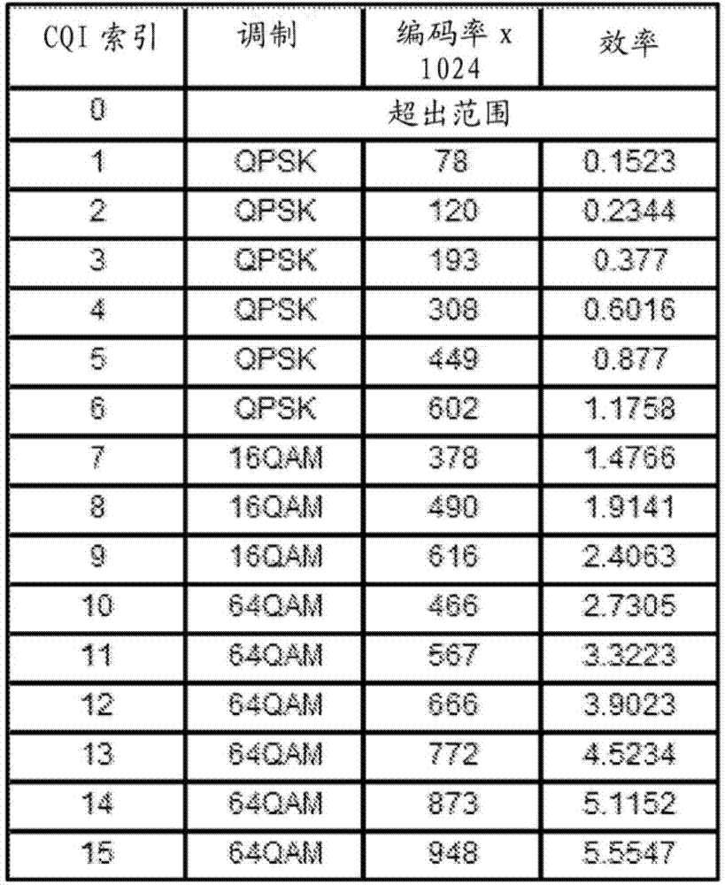
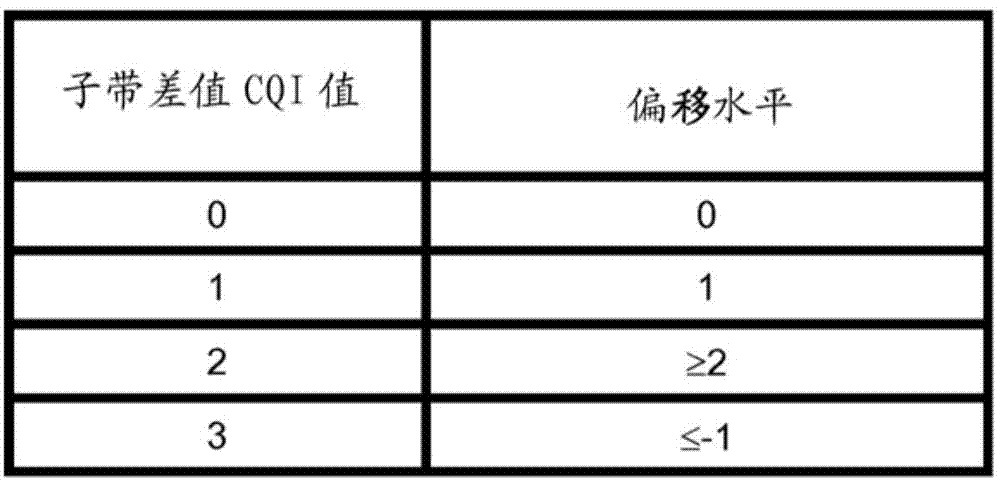
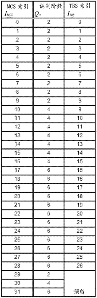
[0115] As mentioned above, the parameters may be various communication parameters such as CQI, difference CQI and / or MCS. Correspondingly, the parameter table may be a CQI table, a difference CQI table and / or an MCS table.
[0116] In addition, if Figure 14 As schematically shown in , the parameter table may at least include a traditional parameter table and an aggressive parameter table, and the aggressive parameter table includes entries related to a new modulation order or a new combination of entries related to a modulation order and a coding rate. Such as Figure 14 The traditional parameter table 1401 shown in may be a table define...
no. 3 example
[0132] Figure 17 is a flowchart illustrating an example implementation of a communication method according to a third embodiment of the present disclosure.
[0133] Such as Figure 17 As shown in , the communication method starts at step 1701, and at step 1701, the same parameter table as in the first embodiment is defined in both the eNode B and the user equipment.
[0134] Next, at step 1702, the eNode B sends an indication to the UE, and the indication jointly represents an entry of the parameter table through legacy bits and at least one unused bit.
[0135] In other words, the third embodiment according to the present disclosure focuses on using unused bits in combination with current bits (eg, MCS bits in DCI) to represent an extended parameter table, such as an extended MCS table.
[0136] Specifically, there are currently 5 bits used for MCS indication in the DCI format. Therefore, in order to represent the extended MCS table without affecting the current MCS bits,...
PUM
 Abstract
Description
Claims
Application Information