
Copying machine with dehumidifying function

A technology of copiers and dehumidifiers, applied in the fields of electric recording technology using charge patterns, equipment for electric recording technology using charge patterns, and electrography, etc., which can solve the problem that copiers do not have the function of oxygen production

Inactive Publication Date: 2015-04-15
SHAANXI BOYUAN SCI & TECH DEV
View PDF0 Cites 0 Cited by
  • Summary
  • Abstract
  • Description
  • Claims
  • Application Information

AI Technical Summary

Problems solved by technology

[0003] The purpose of the invention is to overcome the problem that copiers do not have the function of oxygen production in the prior art

Method used


Image

  • Copying machine with dehumidifying function

Examples


Embodiment 1

[0012] Example 1: Combining Attachment figure 1 describe.

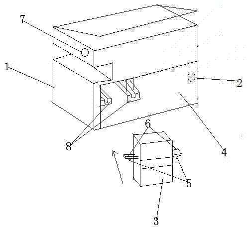
[0013] A copier with dehumidification function includes a copier casing 1 and a built-in power source 2 , and a chamber 4 for accommodating a dehumidifier 3 connected to the power source 2 is formed in the lower part of the casing 1 .

[0014] The solution realizes that the copier has the function of dehumidification.

Embodiment 2

[0015] Example 2, in conjunction with the attached figure 1 describe.

[0016] On the basis of the first embodiment, the chamber 4 is provided with a parallel chute group 2 on the same horizontal line, and the dehumidifier 3 is provided with a slider group 5 matched with the chute group 8 on both sides. The gliding wing group 6. A control button 7 for controlling the dehumidifier 3 is formed on the upper part of the left end of the casing 1 . The front port of the chute group 2 is a blind port.

[0017] The preferred slider group, sliding wing group, control button, and blind port designed at the front end of the chute group can realize the free sliding of the dehumidifier in the front and rear of the chamber, restrict it from sliding out of the chamber, and also control the dehumidifier. work attire.


PUM


Abstract

The invention belongs to the technical field of electric appliances, and provides a copying machine with dehumidifying function. The copying machine comprises a shell and a power supply arranged in the shell; the lower part of the shell is provided with a cavity for holding a dehumidifier connected with the power supply; the cavity is inside provided with slide groove groups which are at a same horizontal line and are parallel; and two sides of the dehumidifier are provided with slide limbs of slide block groups matched with the slide groove groups. The copying machine possesses the dehumidifying function. By preferably selecting the slide block groups, the slide limb groups, a control button, and blind orifices designed at the front end of the slide groove groups, the back-forth free slide of the dehumidifier in the cavity is realized, also the dehumidifier is prevented from sliding out of the cavity, and also the working state of the dehumidifier can be controlled.

Description

technical field [0001] The invention belongs to the technical field of electrical products, in particular to a copier with a dehumidification function. Background technique [0002] The existing office copiers have many functions and single functions, which cannot meet the needs of modern office. In reality, the humidity in many places is relatively high. Too much humidity will be harmful to people working in the office. Especially in the southern regions, dehumidification is a must. However, the existing printing does not have the function of dehumidification, and cannot be used for multiple purposes. In areas or seasons that need dehumidification, how to make the printer not only provide people with office convenience, but also make people's health. Beneficial contributions are an issue worth investigating. SUMMARY OF THE INVENTION [0003] The purpose of the present invention is to overcome the problem that the copier in the prior art does not have the function of prod...

Claims


Application Information

Patent Timeline
Patent Type & Authority Applications(China)
IPC IPC(8): G03G15/00
CPCG03G21/203G03G15/65
Inventor 杨军李杨晓怡
Owner SHAANXI BOYUAN SCI & TECH DEV
Learn More