Continuous casting and rolling device and process for composite plate

A technology of continuous casting, rolling, and cladding plates, applied in metal rolling and other directions, can solve the problems of incapable of continuous cladding production of clad plates, large energy consumption, affecting production efficiency, etc., achieving continuous casting and rolling technology and saving production costs. , the effect of improving production efficiency

Inactive Publication Date: 2015-04-22
YANSHAN UNIV
View PDF4 Cites 18 Cited by
  • Summary
  • Abstract
  • Description
  • Claims
  • Application Information

AI Technical Summary

Problems solved by technology

However, it has been found in the long-term production practice that the above-mentioned hot-rolled composite method needs to clean the surface of several plates to be composited before assembly and welding, and subsequent welding needs to invest a lot of manpower and time. The heating process before rolling also requires a large energy consumption; at the same time, the above method cannot carry out continuous composite production of composite plates, only a single plate can be produced, which greatly affects production efficiency
Therefore, the existing casting and rolling equipment and technology of metal clad sheet can no longer meet the production demand

Method used


Image

  • Continuous casting and rolling device and process for composite plate
  • Continuous casting and rolling device and process for composite plate
  • Continuous casting and rolling device and process for composite plate

Examples


Embodiment Construction

[0032] The present invention will be further described below in conjunction with accompanying drawing:

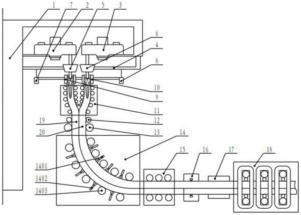
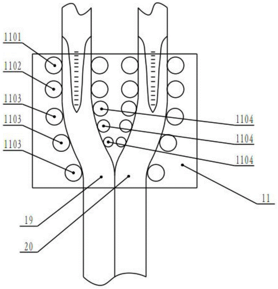
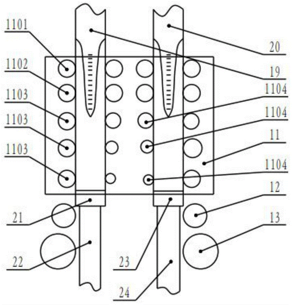
[0033] Such as figure 1 As shown in the overall structure diagram of the equipment of the present invention, the present invention mainly includes a continuous casting machine main body 1, a first ladle turret 2 and a second ladle turret 3, a tundish installation platform 4, a first tundish 5, a second tundish 6. First crystallizer 9, second crystallizer 10, composite zone 11, squeeze roll 12, press roll 13, secondary cooling zone 14, tension leveler 15, flame cutting device 16, descaler 17 and continuous rolling Crew 18,

[0034]The first ladle turret is installed on the top of the main body of the continuous casting machine, a tundish installation platform is installed on the main body of the continuous casting machine below the first ladle turret, the first tundish is installed on the tundish installation platform, and the first tundish is installed on the lower part of...


PUM


Abstract

Disclosed are a continuous casting and rolling device and a process for a composite plate. The device comprises a continuous casting machine body, two steel ladle rotary tables, a tundish mounting platform, two tundishes, two crystallizers, a composite area, a secondary cooling area, extrusion rollers, hold-down rollers, a flame cutting device, a descaling machine, a tension leveler and a continuous rolling unit, the two tundishes are mounted below the different steel ladle rotary tables through the tundish mounting platform, the crystallizers are disposed below the tundishes, the composite area is disposed below the two crystallizers, the extrusion rollers and the hold-down rollers are arranged below the composite area, the secondary cooling area is located below the hold-down rollers, and a horizontal outlet end of the secondary cooling area is sequentially connected with the tension leveler, the flame cutting device, the descaling machine and the continuous rolling unit. The continuous casting and rolling device and the process for the composite plate have the advantages that the width of a composite plate blank can be adjusted, continuous production can be achieved, the process is simple, costs are low, the efficiency is high, operation and controlling are convenient, and the like.

Description

technical field [0001] The invention relates to the field of metallurgical continuous casting and rolling, in particular to continuous casting and rolling equipment and a processing technology for composite plates. Background technique [0002] With the continuous development of science and technology, all walks of life have put forward higher and higher requirements for the use of metal materials. Metal materials composed of a single component can no longer meet the multi-performance requirements in some application fields. It is known that the metal composite plate is a new type of material that combines two or more metals with different properties through temperature and pressure. Metal composite panels are widely used in machinery because they have some characteristics that a single metal does not have. They can give full play to the performance characteristics of each component according to the design requirements. , aviation, chemical industry, navigation and many oth...

Claims


Application Information

Patent Timeline
Patent Type & Authority Applications(China)
IPC IPC(8): B21B1/46B22D11/14B22D11/12
CPCB21B1/466B22D11/12B22D11/1226B22D11/124B22D11/126B22D11/14B22D11/141
Inventor 彭艳赵铁石邢鹏达
Owner YANSHAN UNIV
Why Eureka
Try Eureka