
Discharging device for stamping die

A technology of unloading device and stamping die, which is applied in the direction of pushing out equipment, etc., can solve the problems of difficult unloading of parts and troublesome operation.

Inactive Publication Date: 2015-04-22
马宁
View PDF4 Cites 0 Cited by
  • Summary
  • Abstract
  • Description
  • Claims
  • Application Information

AI Technical Summary

Problems solved by technology

After one stamping, a formed part will be stamped out. The existing stamping die has certain structural defects. It is difficult to remove the stamped and formed parts. It requires manpower to take out the parts, which is very troublesome to operate.

Method used


Image

  • Discharging device for stamping die
  • Discharging device for stamping die

Examples


Embodiment Construction

[0012] The present invention is described in further detail now in conjunction with accompanying drawing. These drawings are all simplified schematic diagrams, which only illustrate the basic structure of the present invention in a schematic manner, so they only show the configurations related to the present invention.

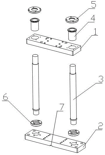
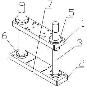
[0013] Such as figure 1 and figure 2 The shown unloading device for the stamping die includes an upper top plate 1 and a lower bottom plate 2, an elastic block is arranged between the upper top plate 1 and the lower bottom plate 2, and two supporting rods 3 are pierced on the upper top plate 1 and the lower bottom plate 2 , the upper top plate 1 is sequentially provided with two fixing sleeves 4 and the first fixing gasket 5 passing through the support rod 3 from bottom to top, and the lower bottom plate 2 is provided with two second fixing gaskets 6 passing through the supporting rod 3 .

[0014] Further definition: the elastic block arranged between the ...


PUM


Abstract

The invention relates to the technical field of discharging devices, and in particular relates to a discharging device for a stamping die. The device comprises an upper top plate and a lower bottom plate; an elastic block is arranged between the upper top plate and the lower bottom plate; two supporting rods pass through the upper top plate and the lower bottom plate; a fixing sleeve and a first fixing spacer which respectively pass through the supporting rods are arranged on the upper top plate from bottom to top in a sequence; a second fixing spacer which passes through the supporting rods is arranged on the lower bottom plate. According to the discharging device for the stamping die, a stamping part can be sprung out through the elastic block after being downwards compressed through a pressing machine, so that the discharging effect can be achieved.

Description

technical field [0001] The invention relates to the technical field of unloading devices, in particular to an unloading device for stamping dies. Background technique [0002] Stamping die is a special process equipment for processing materials into parts in cold stamping processing. Once stamping is completed, a formed part will be stamped out. The existing stamping dies have certain structural defects, and the stamped and formed parts are difficult to remove. Manpower is needed to take out the parts, which is very cumbersome to operate. Contents of the invention [0003] The technical problem to be solved by the present invention is: In order to solve the problems raised in the above background technology, the present invention provides a stamping die unloading device, which ejects the stamping parts by means of elastic blocks after being pressed down by the press, so as to achieve The effect of unloading. [0004] The technical solution adopted by the present inventi...

Claims


Application Information

Patent Timeline
Patent Type & Authority Applications(China)
IPC IPC(8): B21D45/04
Inventor 马宁
Owner 马宁
Learn More