A glass fiber yarn auxiliary cutting device
A cutting device and glass fiber yarn technology, which is applied in the cutting of textile materials, textiles and papermaking, etc., can solve the problems of uneven cutting and failure to realize the flat placement of glass fiber yarn, and achieve the effect of avoiding tool scratches
- Summary
- Abstract
- Description
- Claims
- Application Information
AI Technical Summary
Problems solved by technology
Method used
Image
Examples
Embodiment 1
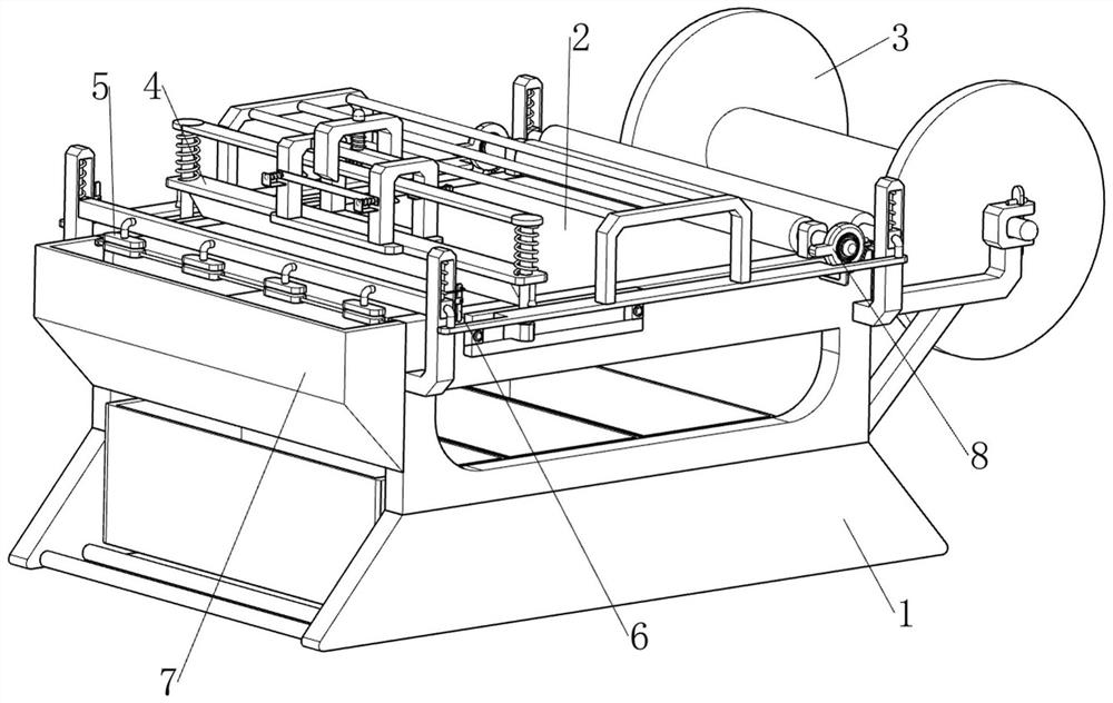
[0071] A glass fiber yarn auxiliary cutting device, such as figure 1As shown, it includes a first support frame 1, a workbench 2, a blanking assembly 3 and a cutting assembly 4, and a workbench 2 is connected between the two first support frames 1, and between the right parts of the two first support frames 1 A blanking assembly 3 is provided, and a cutting assembly 4 is provided between the two first support frames 1 .
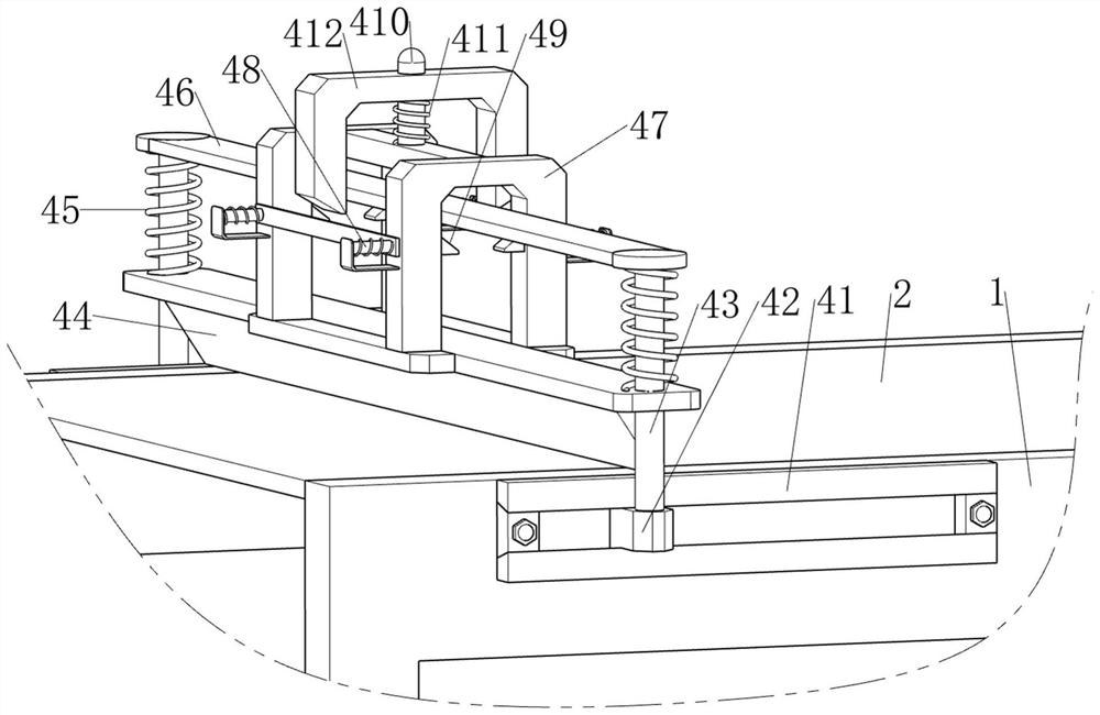
[0072] When people need to cut the glass fiber yarn, they can use this glass fiber yarn auxiliary cutting device. First, people wind the glass fiber yarn on the blanking assembly 3, and then pull one end of the glass fiber yarn to the left side of the workbench 2. , and then people move the cutting assembly 4, and the cutting assembly 4 moves to cut the glass fiber yarn.
Embodiment 2
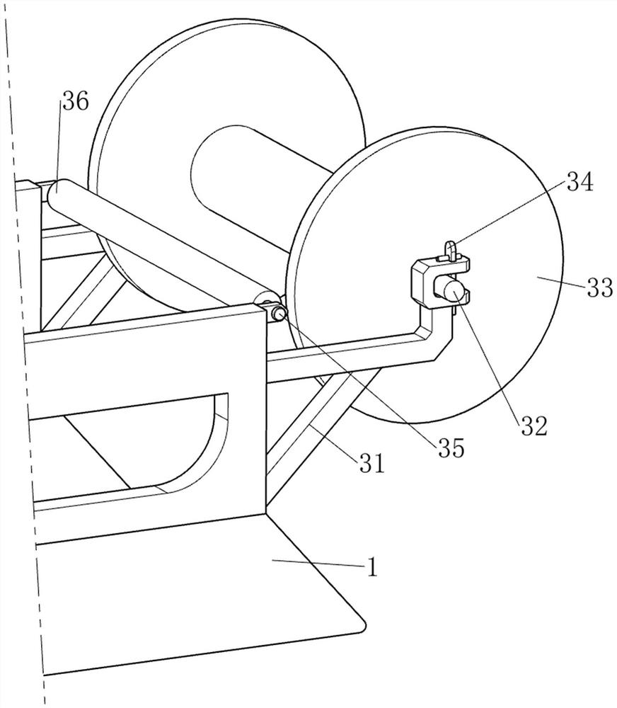
[0074] On the basis of Example 1, such as figure 2 and image 3 As shown, the blanking assembly 3 includes a second support frame 31, a first rotating shaft 32, a raw material cylinder 33, a limit block 34, a second rotating shaft 35 and a guide cylinder 36, and the right parts of the two first supporting frames 1 are provided with The second support frame 31, the first rotating shaft 32 is arranged in rotation between the two second supporting frames 31, the raw material cylinder 33 is arranged on the first rotating shaft 32, and the first supporting frame 1 is slidingly provided with a limit block 34 on the right side, A second rotating shaft 35 is rotatably arranged between the right parts of the two first support frames 1 , and a guide cylinder 36 is arranged on the second rotating shaft 35 .
[0075] People wind the glass fiber yarn on the raw material cylinder 33, then pull one end of the glass fiber yarn through the lower side of the guide cylinder 36 and then pull it...
Embodiment 3
[0079] On the basis of Example 2, such as Figure 4-7 As shown, it also includes a compression assembly 5, and the compression assembly 5 includes a second support rod 51, a third slide block 52, a second telescopic rod 53, a compression cylinder 54, a connecting frame 55, a compression block 56 and a push Bar 57, the first support frame 1 left and right sides are all provided with the second support bar 51, the sliding type is provided with the 3rd slide block 52 on the second support bar 51, establishes between the 3rd slide block 52 and the second support bar 51 There is a second telescopic rod 53, the second telescopic rod 53 is made up of a telescopic rod and a spring, a spring is connected between the third slider 52 and the second support rod 51, and the spring is wound on the telescopic rod, and the two third rods on the right side Between the slide block 52, the rotary type is provided with a compression cylinder 54, and a connecting frame 55 is connected between the ...
PUM
 Abstract
Description
Claims
Application Information
 - R&D
- Intellectual Property
- Life Sciences
- Materials
- Tech Scout
- Unparalleled Data Quality
- Higher Quality Content
- 60% Fewer Hallucinations
Browse by: Latest US Patents, China's latest patents, Technical Efficacy Thesaurus, Application Domain, Technology Topic, Popular Technical Reports.
© 2025 PatSnap. All rights reserved.Legal|Privacy policy|Modern Slavery Act Transparency Statement|Sitemap|About US| Contact US: help@patsnap.com


