
A Coarse and Thin Connection System Layout

An interconnected system and layout technology, applied in the direction of textiles and papermaking, can solve the problems of lack of consistency and versatility, troublesome management of roving varieties, unfavorable labor costs, etc., and achieve the effects of simple structure, improved production efficiency, and simple control

Active Publication Date: 2018-08-24
WUXI HONGYUAN ELECTROMECHANICAL TECH
View PDF6 Cites 0 Cited by
  • Summary
  • Abstract
  • Description
  • Claims
  • Application Information

AI Technical Summary

Problems solved by technology

The current system layout is based on the different types of spinning, re-arranging different thickness and fineness conveying systems. The management of roving types is troublesome, which seriously affects production efficiency and is not conducive to reducing labor costs, and the entire system layout also lacks consistency and versatility.

Method used


Image

  • A Coarse and Thin Connection System Layout
  • A Coarse and Thin Connection System Layout
  • A Coarse and Thin Connection System Layout

Examples


Embodiment 1

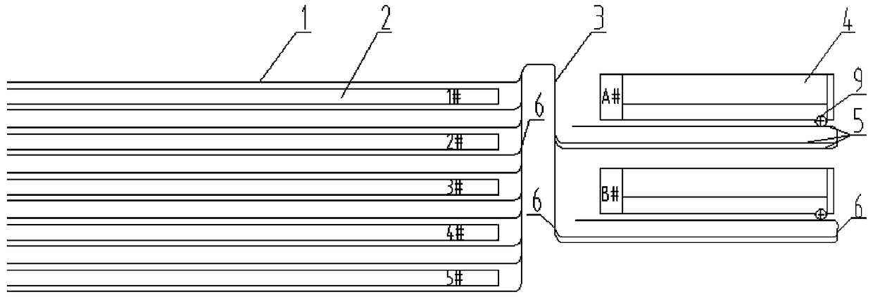
[0015] Embodiment 1: as figure 1 As shown in the figure, a layout of thick and thin interlinked system, including five spinning frames 2 (1#, 2#, 3#, 4#, 5#), each spinning frame corresponds to two rails for a total of ten spinning frames 1, respectively spinning A Two roving frames 4 of the B variety roving and the empty and full tube warehouses 5 corresponding to each roving frame one by one, each empty and full tube warehouse 5 includes an empty tube track 51 and two full tube tracks 52,53, two One end of the full tube track 52, 53 is connected to the empty tube track 51 through the track splitting device 6, and the other end is connected to the main track 3 through the track splitting device 6, and the main track 3 is connected to the spinning frame track 1 through the track splitting device 6. Connected, the empty tube track 51 is connected with the roving frame 4 through the empty and full tube switch 9.

[0016] Such as image 3 As shown, the system transfers the empt...

Embodiment 2

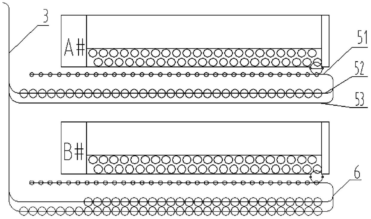
[0021] Embodiment 2: as figure 2 As shown, the working principle is roughly the same as that of Embodiment 1, except that one end of the empty pipe track 51 is connected to two full pipe tracks 52 through the track separation and closing device 6, and the other end is directly connected to the main track 3 through the track separation and closing device 6. connected. Therefore, the empty tubes used up on the spinning frame 2 can directly enter the empty tube track of the roving frame 4 through the main track 3 and wait to be exchanged with the full yarn on the roving frame 4 without passing through two full yarn tracks 52 or 53. This method is sufficient With the effective connection between the tracks, the spinning efficiency can be further improved.


PUM


Abstract

The invention provides a roving and spinning unit system layout. The roving and spinning unit system layout comprises spinning frames, spinning frame rails, roving frames, roving frame rails and a main rail allowing the spinning frame rails and the roving frame rails to be connected. Each roving frame rail is a bare and full bobbin magazine formed by at least three bare bobbin rails holding bare bobbins and a full bobbin rail holding full bobbins. The bare and full bobbin magazines correspond to the roving frames in a one-to-one mode, and all the bare and full bobbin magazines and all the spinning frame rails are movably connected with the main rail. According to the roving and spinning unit system layout, the bare and full bobbin magazines are correspondingly arranged on all the roving frames, and the rail capacity of each bare and full bobbin magazine allows the corresponding roving frame to use. Accordingly, rail space is fully utilized, no integrated yarn magazine is required, while the comprehensive effect far surpasses the function of the integrated yarn magazine, and the difficulties in identification of roving varieties and communication in the prior art are overcome. The varieties of stored yarn of each yarn magazine will not be confused, no matter whether a single variety or multiple varieties or varieties which is the replacement process for production will not bring inconvenience to production management, control is easy and quick, and therefore production efficiency is improved.

Description

technical field [0001] The invention relates to the field of cotton textile machinery, in particular to a combined system of a roving frame and a spinning frame. Background technique [0002] With the improvement of the degree of automation of textile machinery, the thick and thin combined conveying method has been widely used, and the layout of the thick and thin combined conveying system has become particularly important. The current system layout is based on the different types of spinning, re-arranging different thickness and fineness conveyor systems. The management of roving types is troublesome, which seriously affects production efficiency and is not conducive to reducing labor costs, and the entire system layout lacks consistency and versatility. Contents of the invention [0003] Purpose of the invention: The purpose of the present invention is to provide a layout of the thick-thinning system that can spin yarns of many varieties and quantities in view of the def...

Claims


Application Information

Patent Timeline
Patent Type & Authority Patents(China)
IPC IPC(8): D01H9/02
CPCD01H9/02
Inventor 刘许红张啸冬张巍
Owner WUXI HONGYUAN ELECTROMECHANICAL TECH
Learn More