Vibration rod guiding device

A technology of guiding device and vibrating rod, which is applied in the direction of construction, building structure, and building material processing, etc., and can solve the problems of formwork friction, difficult insertion of vibrating rods, and failure of vibrating rods to be correctly positioned.

Inactive Publication Date: 2015-04-22
ZHEJIANG THERMAL POWER CONSTR
View PDF5 Cites 6 Cited by
  • Summary
  • Abstract
  • Description
  • Claims
  • Application Information

AI Technical Summary

Problems solved by technology

[0003] Aiming at the problems that the current vibrating rod is difficult to insert, the vibrating rod cannot be correctly positioned, it is easy to rub against the template, and it is easy to cause the dead angle

Method used


Image

  • Vibration rod guiding device
  • Vibration rod guiding device
  • Vibration rod guiding device

Examples


Embodiment 1

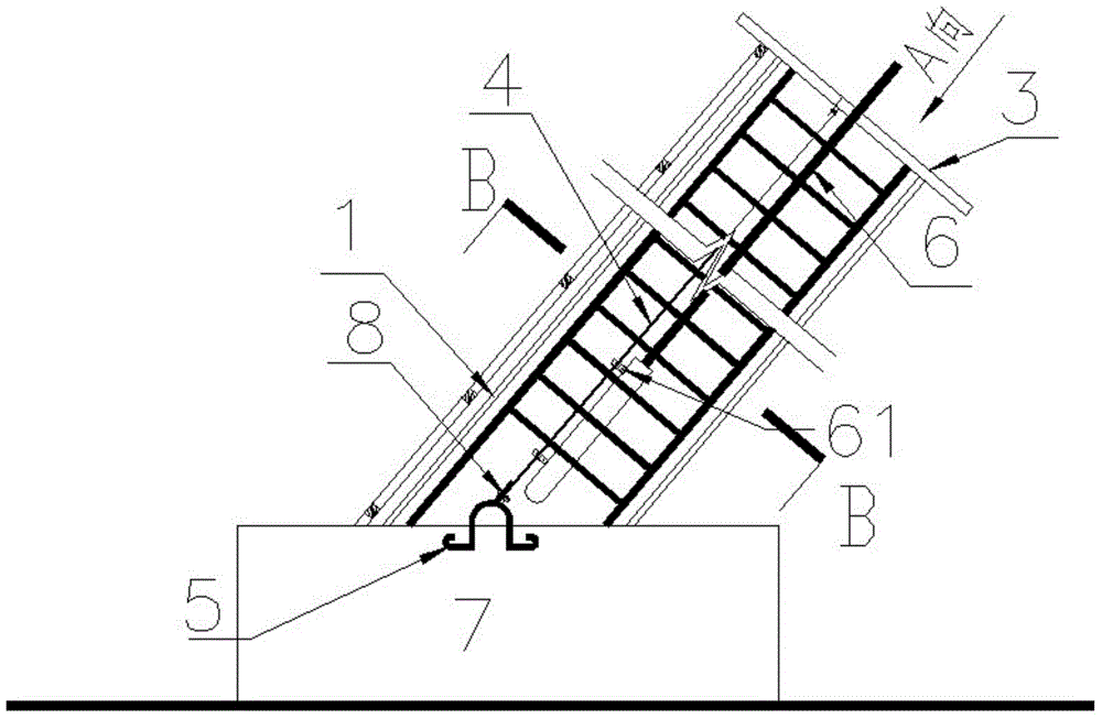
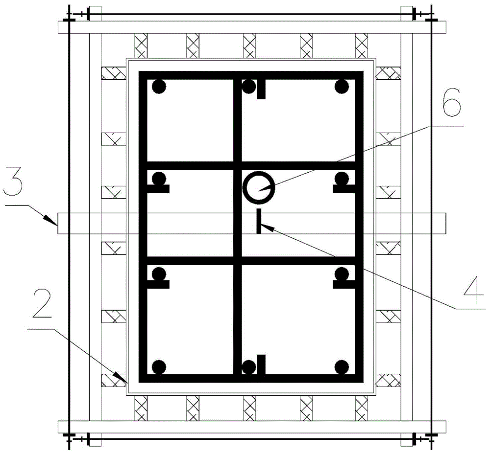
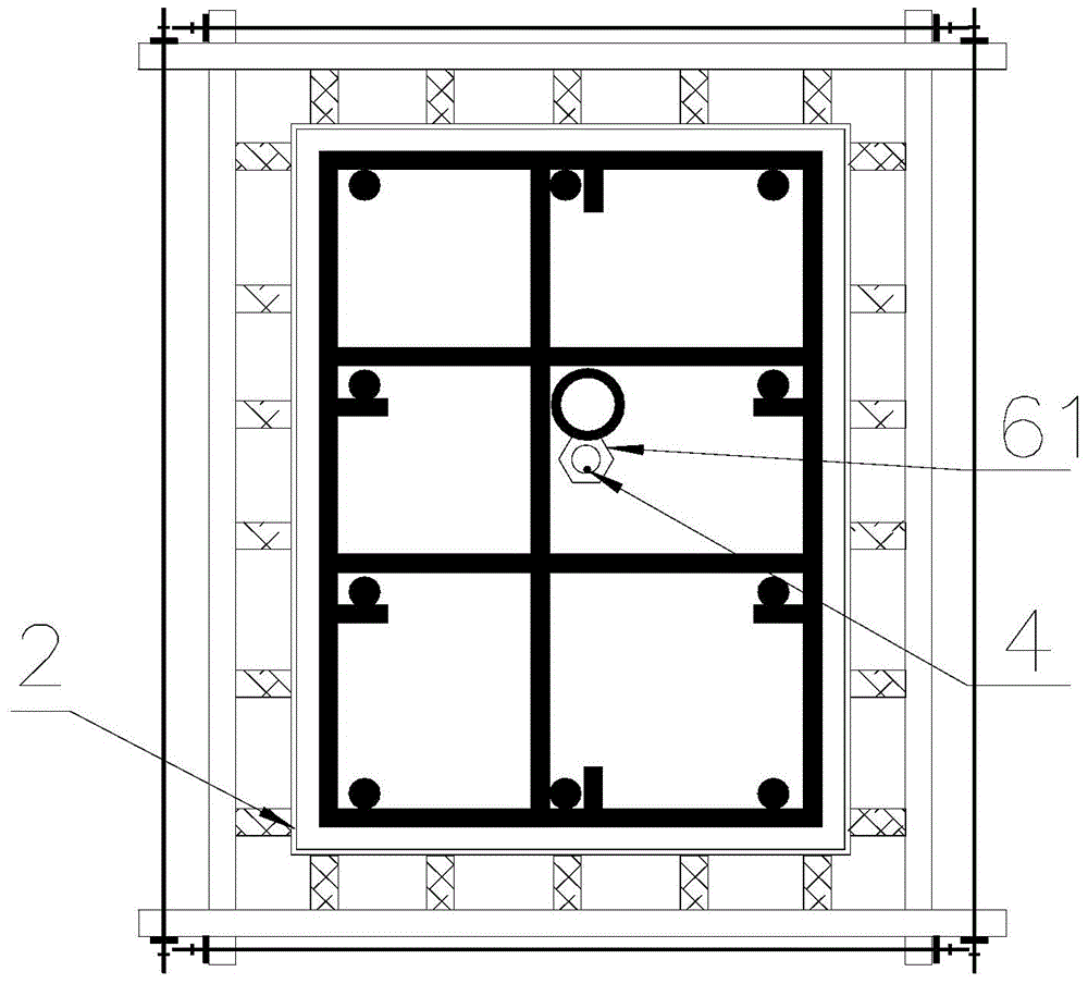
[0019] Embodiment 1 The vibrator guide device of the present invention includes an outer frame 1, a cross arm 3, a guide wire rope 4, and a pre-embedded collar 5 that are set outside the formwork frame 2. The bottom of the outer frame 1 is fixed on the On the corresponding foundation 7 at the bottom of the vibrating rod 6, and the embedded collar 5 is fixed on the foundation 7; the cross arm 3 is fixed on the top of the outer frame 1, and the side of the vibrating rod 6 A plurality of guide rings 61 for penetrating guide wire ropes are arranged in the axial direction of the wall; the bottom of the guide wire rope 4 is fixed on the embedded collar 5, and the upper end passes through the guide rings 61 and is fixed on the cross arm 3 to keep the whole The guide wire rope 4 is under tension.

[0020] The outer frame 1 is in the same shape as the formwork frame 2 surrounding the vibrating rod 6, and the cross section is square.

[0021] The central axis of the cross arm 3 is perp...


PUM


Abstract

Disclosed is a vibration rod guiding device. The vibration rod guiding device comprises an outer frame which sleeves a template frame, a cross arm, a guiding steel wire rope and an embedded lantern ring, wherein the bottom of the outer frame is fixed on a corresponding foundation at the bottom of a vibration rod, the embedded lantern ring is fixed on the foundation, the cross arm is fixed at the top of the outer frame, a plurality of guiding rings used for the guiding steel wire rope to pass through are arranged in the axial direction of the side wall of the vibration rod, the bottom of the guiding steel wire rope is fixed on the embedded lantern ring, the upper end of the guiding steel wire rope passes through the guiding rings and is fixed on the cross arm, and then the whole guiding steel wire rope is kept in a tensioning state. The vibration rod guiding device has the advantages of being capable of controlling the moving direction of the concrete vibration rod, solving the problems that the vibration rod is stuck or rub a template, a vibration dead angle is generated and the like in construction of a concrete member, and solving the problem that the concrete vibration rod is difficultly placed on a proper position when inserted into the reinforced concrete member.

Description

technical field [0001] The invention relates to a vibrating rod guiding device. Background technique [0002] The specifications and forms of reinforced concrete components in power plant buildings are various. For example, the herringbone column of the cooling tower structure is an inclined reinforced concrete component and is also a narrow and long concrete component. In the power plant building, the main transformer firewall and various pool walls are mostly Thin-shell reinforced concrete components, during the concrete pouring process of such components, due to the difficulty of inserting the vibrating rod, the vibrating rod is stuck in the construction of the concrete component or rubbed against the formwork, resulting in quality problems caused by concrete vibration. more and more. During the construction of conventional cooling tower herringbone columns, the vibrating rods cannot be positioned correctly due to the inclined and small section size of the herringbone co...

Claims


Application Information

Patent Timeline
IPC IPC(8): E04G21/08
Inventor 潘巨忠何广章蒋勇鸿姚伟锋韩飞腾
Owner ZHEJIANG THERMAL POWER CONSTR
Why Eureka
Try Eureka