Hydraulic support balancing mechanism testing device and method

A technology of hydraulic support and balancing mechanism, which is applied to the testing of machine/structural components, measuring devices, mine roof supports, etc., can solve the problem that the balancing mechanism does not have a good test method, and achieve the effect of good verification and reduction of underground accidents.

Inactive Publication Date: 2015-04-22
CHINA COAL BEIJING COAL MINING MACHINERY
View PDF7 Cites 0 Cited by
  • Summary
  • Abstract
  • Description
  • Claims
  • Application Information

AI Technical Summary

Problems solved by technology

[0003] In the prior art, there is no good test method for the balance mechanism

Method used


Image

  • Hydraulic support balancing mechanism testing device and method
  • Hydraulic support balancing mechanism testing device and method

Examples


specific Embodiment approach

[0020] The above-mentioned hydraulic support balance mechanism test device of the present invention realizes the method for hydraulic support balance mechanism test, and its preferred specific implementation mode is:

[0021] Include steps:

[0022] Firstly, the cover beam, the front connecting rod, the rear connecting rod and the base of the hydraulic support are fixed to each other;

[0023] Then, first raise the column to make the top beam upward, the balance jack rod chamber is pulled until the safety valve is unloaded and pulled out at least 30mm, then the column is lowered to lower the top beam, and the balance jack piston chamber is pressed until the safety valve is unloaded and is pushed back at least 30mm , The lifting of the column is a cycle, and the total cycle is at least 4000 times.

[0024] Time is used to control the expansion and contraction of the balance jack, and the average time for stretching out 30mm is obtained through experiments to set the time for l...

specific Embodiment

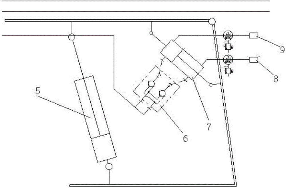
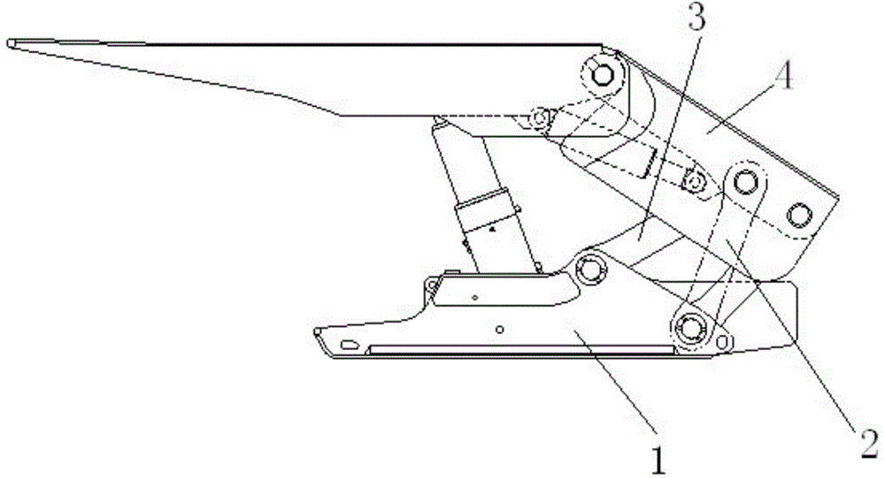
[0026] Such as figure 1 , figure 2 As shown, the rear part of the bracket is properly fixed. Firstly, the column is raised to make the top beam upward, and the rod chamber of the balance jack is pulled until the safety valve is unloaded and pulled out at least 30mm. Unloaded and pressed back at least 30mm. The lifting of the column is a cycle, a total of 4000 cycles.

[0027] According to the limitations of the pipeline system of the test bench, the test bench has no displacement sensor. Consider using time to control the expansion and contraction of the balance jack. The control is: liquid filling-lowering column, pressurization-rising column, the initial support and lowering column respectively replenish the upper and lower chambers of the balance, while the column is raised, the upper chamber of the balance jack is pressurized, the safety valve drains, and the system supplies the lower chamber. When the chamber is replenished with liquid, the balance jack is stretched o...


PUM


Abstract

The invention discloses a hydraulic support balancing mechanism testing device and method. A hydraulic support comprises a top beam, a caving shield, a base, a stand column, a front connecting rod, a rear connecting rod and a balancing jack. The front connecting rod on one side of the hydraulic support is detached first, and the hinge point of the upper end of the rear connecting rod on the same side and the caving shield is assembled at the hinge point of the upper end of the existing front connecting rod and the caving shield after being detached so that the hinge points can be fixed to each other; then, the stand column is lifted first so that the top beam can be lifted upwards, a rod cavity of the balance jack is pulled out by at least 30 mm till a safety valve is unloaded, then the stand column is lowered so that the head of the top beam can be lowered, and a piston cavity of the balance jack is pressed by at least 30 mm till the safety valve is unloaded; a cycle is completed after the stand column rises and falls one time, and at least 4000 cycles are completed. The telescopic amount of the balance jack is controlled through time, and the experiment shows that the average time for extending by 30 mm is set as the liquid supply time. The strength of a balance mechanism can be well verified, and downhole accidents are reduced.

Description

technical field [0001] The invention relates to a detection technology of a balance mechanism on a hydraulic support for coal mines, in particular to a test device and method for a balance mechanism of a hydraulic support. Background technique [0002] The balance mechanism of the two-column shielded hydraulic support plays a vital role in the two-column shielded hydraulic support. With the vigorous promotion and application of two-column shielded high-end hydraulic supports in high-yield and high-efficiency working faces, the test for the balance mechanism is becoming more and more important. : In general technical condition ", there is no this item to the balance mechanism inspection item on the coal mine hydraulic support. [0003] In the prior art, there is no good test method for the balance mechanism. Contents of the invention [0004] The object of the present invention is to provide a hydraulic support balance mechanism test device and method with good experiment...

Claims


Application Information

Patent Timeline
Patent Type & Authority Applications(China)
IPC IPC(8): E21D23/04E21D23/16G01M99/00
CPCE21D23/04E21D23/16G01M99/00
Inventor 刘顺斌刘国柱包冬生李晓丽康远宁段志军
Owner CHINA COAL BEIJING COAL MINING MACHINERY
Why Eureka
Try Eureka