Test loading system for tendon connector of tension leg platform

A technology of tension leg platform and loading system, which is applied in the testing of machines/structural components, the use of stable tension/compression to test the strength of materials, and the testing of mechanical components. It can solve the problem that fixed foundations cannot meet the requirements of deep-sea wind energy development. , non-applicability, self-weight and project cost increase, etc., to achieve the effect of verifying fatigue resistance, reliability and good economy

Pending Publication Date: 2019-02-01
CCCC THIRD HARBOR ENG +2
View PDF1 Cites 2 Cited by
  • Summary
  • Abstract
  • Description
  • Claims
  • Application Information

AI Technical Summary

Problems solved by technology

With the development of near-shore offshore wind farms, the offshore distance and water depth of wind farms continue to increase, and various traditional fixed foundations have been difficult to meet the requirements of deep-sea wind energy development.
The construction of wind farms will gradually develop in deeper waters. If a fixed foundation is used in offshore wind farms in deep seas, its dead weight and engineering cost will increase significantly with the water depth, so it is not suitable for deep sea environments

Method used


Image

  • Test loading system for tendon connector of tension leg platform
  • Test loading system for tendon connector of tension leg platform
  • Test loading system for tendon connector of tension leg platform

Examples


Embodiment Construction

[0018] The present invention will be further described below in conjunction with accompanying drawing.

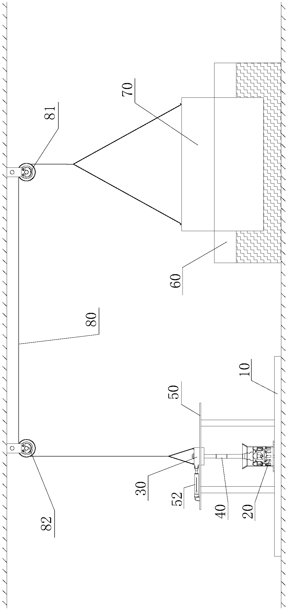
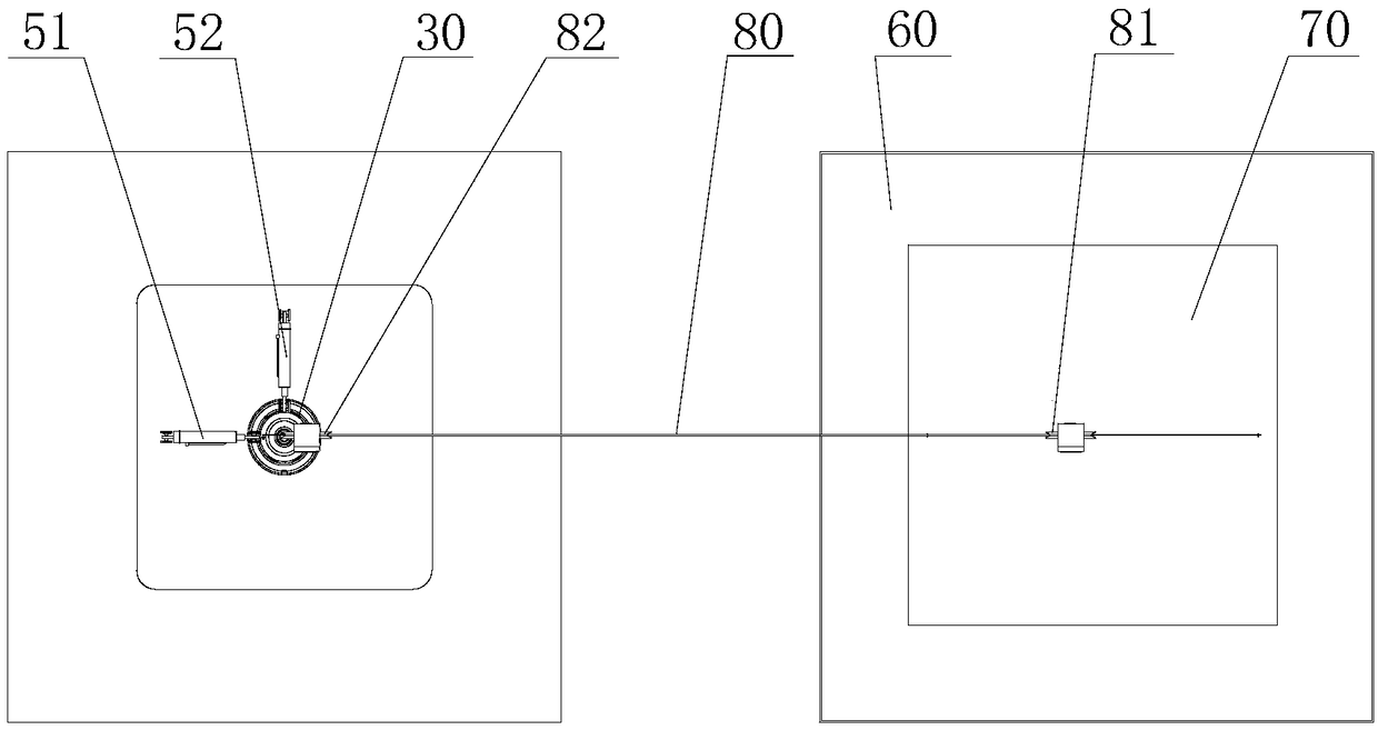
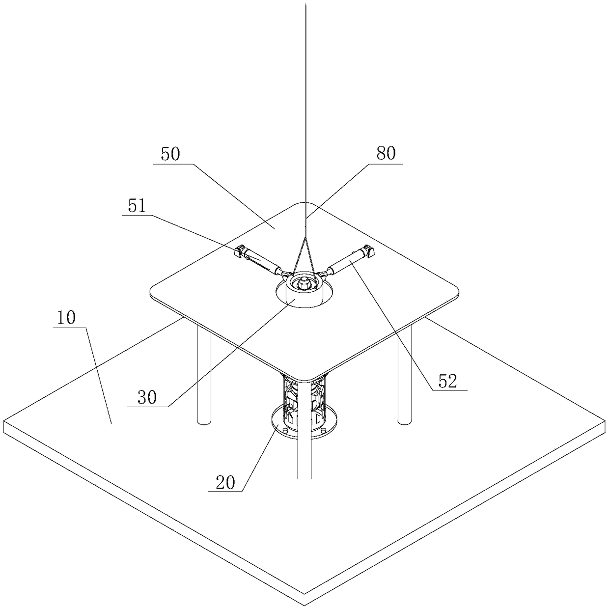
[0019] see Figure 1 to Figure 5 , the test loading system of the tension leg platform tendon connector of the present invention includes a base 10, a tendon connector 20, a top connector 30, a loading unit and a load unit.

[0020] The tendon connector 20 is fixed on the upper surface of the base 10 by screws;

[0021] The top connector 30 is coaxially connected above the tendon connector 20 through a quick joint 40;

[0022] The upper end of the tendon connector 20 and the lower end of the top connector 30 lead out the lower ball shaft and the upper ball shaft in one-to-one correspondence, so that the lower ball shaft and the upper ball shaft can swing about 10° in any direction; The quick joint 40 is connected between the upper end of the lower ball stud shaft and the lower end of the upper ball stud shaft.

[0023] The loading unit includes a loading platform 50 and ...


PUM


Abstract

The invention discloses a test loading system for a tendon connector of a tension leg platform. The test loading system comprises a tendon connector, a base, a top end connector, a loading unit and aload unit. The tendon connector is fixed on the upper surface of the base. The top end connector is coaxially connected above the tendon connector through a quick joint. The loading unit comprises a loading platform and two loading oil cylinders. The loading platform is provided above the base, and has a through hole at the position corresponding to the top connector, so that the top end connectoris located in the through hole. The two loading oil cylinders are mounted on the loading platform, and vertically hinged to the top end connector. The load unit comprises a water tank and a load block. The water tank is provided on one side of the loading platform. The load block is provided in the water tank in a floating manner. The load block is connected with the top end connector through a steel wire rope and two fixed pulleys. The test loading system of the invention can simulate real sea working conditions to verify the strength, the fatigue resistance, the reliability and the like oftendon connectors.

Description

technical field [0001] The invention relates to a test loading system for a tension leg platform tendon connector. Background technique [0002] At present, the offshore wind farms that have been built in China all use offshore wind turbines with offshore fixed foundations. With the development of near-shore offshore wind farms, the offshore distance and water depth of wind farms continue to increase, and various traditional fixed foundations have been difficult to meet the requirements of deep-sea wind energy development. The construction of wind farms will gradually develop in deeper waters. If a fixed foundation is used in offshore wind farms in deep seas, its dead weight and engineering cost will increase significantly with water depth, so it is not suitable for deep sea environments. The floating wind turbine adopts the floating foundation and mooring system, which can adapt to a larger water depth environment. Compared with the fixed offshore wind turbine, the manufac...

Claims


Application Information

Patent Timeline
Patent Type & Authority Applications(China)
IPC IPC(8): G01N3/10G01M13/00
CPCG01M13/00G01N3/10G01N2203/0017G01N2203/0048
Inventor 张继彪陆晨雷马振江王何汇陈韬杨三元陆泽城
Owner CCCC THIRD HARBOR ENG
Why Eureka
Try Eureka