Intersection bus stop overflow control method
A technology of bus stops and control methods, which is applied in the direction of controlling traffic signals, etc., can solve the problems of decreased operating efficiency at intersections, social vehicle delays, and increased parking times, and achieves the effect of a wide range of applications
- Summary
- Abstract
- Description
- Claims
- Application Information
AI Technical Summary
Problems solved by technology
Method used
Image

Examples
Embodiment 1
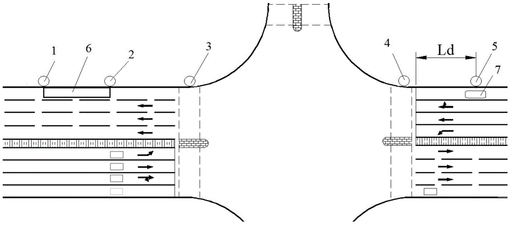
[0049] Set multiple detectors at an intersection, the layout of the detectors is as follows figure 2 As shown in , wherein, the first detector 1 is used for counting and recording the situation of the bus leaving the station, the second detector 2 is used for detecting whether the last bus parking space is occupied, and the third detector 3 is used for detecting waiting to enter the first bus parking space. Whether the bus at a stop is full of roads and overflows, the fourth detector 4 is located at whether the bus drives to the stop line, and the fifth detector 5 is used to detect the arrival of the bus.
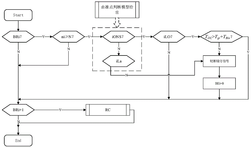
[0050] figure 1 For the overflow control core logic flow of this embodiment, figure 1 Among them, BRi indicates that the signal light in the running direction of No. 111 bus 7 is a green light signal, iONS indicates that bus 7 of No. 111 arrives at stop 6 on time, iLa indicates that bus 7 of No. 111 arrives at stop 6 late, and iLO indicates that bus 7 of No. 111 arrives a...
Embodiment 2
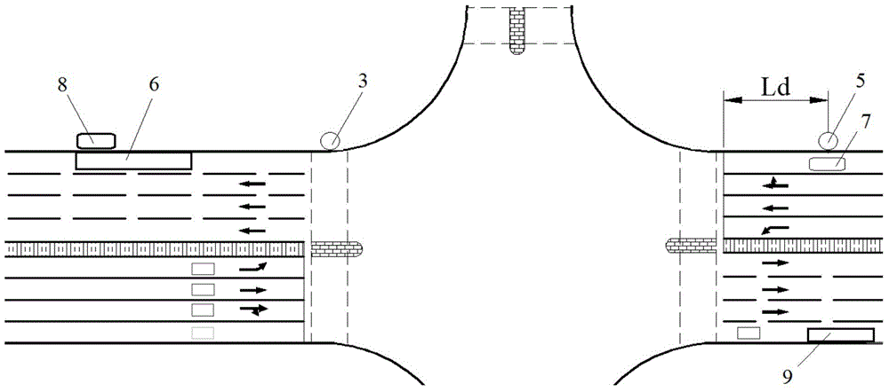
[0080] The significant difference between this embodiment and Embodiment 1 is that in this embodiment, three detectors are arranged at a certain intersection, such as image 3 , wherein the sixth detector is used to detect whether there is a vacancy at the bus stop 6, the third detector 3 is used to detect whether the bus waiting to enter the first bus stop is full of roads and overflows, and the fifth detector 5 is used for Detect bus arrivals.
[0081] Based on the above-mentioned equipment, a kind of intersection bus stop overflow control method of the present invention is used to control, comprising steps:
[0082] A. When the No. 111 bus 7 that needs to enter the first stop 6 is approaching the intersection, that is, when it is captured by the fifth detector, whether the signal light in the direction of travel of the No. 111 bus 7 is a green light, and if yes, then Execute step B, if not, end overflow control;
[0083] B. Determine whether the 111 bus 7 is on time, if y...
Embodiment 3
[0112] The similarities between this embodiment and the second embodiment will not be described, and only the differences will be described.
[0113] The significant difference between the present embodiment and the second embodiment is that in the present embodiment, after the overflow control of the docking station 6 is completed, for example image 3 Intermediate stop 9 carries out overflow control.
PUM
 Abstract
Description
Claims
Application Information
 - R&D
- Intellectual Property
- Life Sciences
- Materials
- Tech Scout
- Unparalleled Data Quality
- Higher Quality Content
- 60% Fewer Hallucinations
Browse by: Latest US Patents, China's latest patents, Technical Efficacy Thesaurus, Application Domain, Technology Topic, Popular Technical Reports.
© 2025 PatSnap. All rights reserved.Legal|Privacy policy|Modern Slavery Act Transparency Statement|Sitemap|About US| Contact US: help@patsnap.com