
Mold laser adjusting scale

A laser and mold technology, applied in the field of adjusting ruler, can solve the problems of inability to see the adjustment degree, difficult to master, etc.

Inactive Publication Date: 2015-04-29
JIHUA 3515 LEATHER & SHOES
View PDF4 Cites 3 Cited by
  • Summary
  • Abstract
  • Description
  • Claims
  • Application Information

AI Technical Summary

Problems solved by technology

Sometimes there may only be an adjustment amount of one millimeter, which is difficult to grasp, especially in low light conditions, and the adjustment degree cannot be seen clearly

Method used


Image

  • Mold laser adjusting scale
  • Mold laser adjusting scale
  • Mold laser adjusting scale

Examples


Embodiment Construction

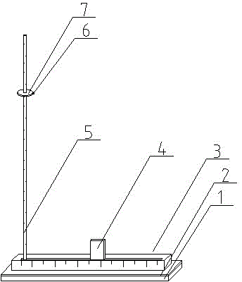
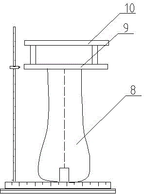
[0011] Such as figure 1 The shown mold laser calibration ruler includes a base 2 mounted on a magnetic base 1 . The magnetic base can be adsorbed to the surface of metal objects, stably ensuring accurate measurement results. The base 2 is provided with a support 3, the support 3 is a support with a horizontal scale, the upper surface of the support 3 is provided with a bar-shaped groove, and the centerline laser projector 4 is arranged in the bar-shaped groove through a slider, which is convenient Move the centerline laser projector to the centerline position of the iron foot mould, set a vertical scale bar 5 on the left end of the strip groove, and set a laser projection lamp on the vertical scale bar 5, and the laser head on the laser projection lamp is dot-shaped The laser head 6, the laser projection lamp is arranged on the vertical scale rod 5 through the slider 7, the middle of the slider is provided with a mounting hole matching with the vertical scale rod, and the sli...


PUM


Abstract

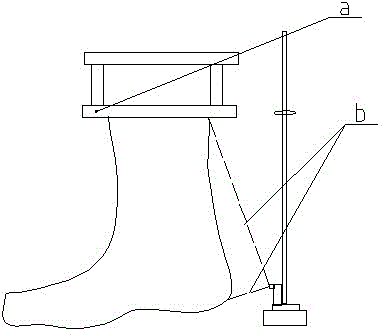
A mold laser adjusting scale comprises a base. A support is arranged on the base. An elongated groove is formed in the upper surface of the support. A center-line laser projector is arranged in the elongated groove through a slide block. A vertical scale rod is arranged at the left end of the elongated groove and provided with a laser projecting lamp. A laser head of the laser projecting lamp is a point-like laser head. The laser projecting lamp is arranged on the vertical scale rod through the slide block. A mounting hole is formed in the center of the slide block and matched with the vertical scale rod. The slide block is in clearance fit with the vertical scale rod. The slidable center-line laser projector and the fixed vertical scale rod are arranged on the support. The center line of the mold is determined by the aid of the support with scales and the center-line laser projector. With one angle of a mold steel plate as a reference standard, the laser projecting lamp arranged on the vertical scale rod can horizontally rotate by 360 degrees so as to measure whether or not the rest three angles of the steel plate are same in height, if not, adjustment is performed. The mold laser adjusting scale is accurate to adjust and convenient to operate.

Description

technical field [0001] The invention relates to an adjustment tool belonging to the shoemaking industry, in particular to an adjustment ruler used for iron foot mold installation. Background technique [0002] In the shoemaking industry, the installation of the iron foot mold is supported by four screws between the upper and lower steel plates 10 and 9. Adjusting the four screws can adjust the vertical degree of the iron foot, the required offset, and the pressure of the iron foot. depth. Sometimes there may only be an adjustment amount of one millimeter, which is difficult to grasp, especially in low light conditions, and the adjustment degree cannot be seen clearly. Contents of the invention [0003] The purpose of the present invention is to overcome the above-mentioned shortcomings and provide a mold laser calibration ruler, which uses the good linearity and focus of the laser for measurement and accurate adjustment. [0004] To achieve the above object, the present...

Claims


Application Information

Patent Timeline
Patent Type & Authority Applications(China)
IPC IPC(8): A43D1/00
Inventor 陈虎
Owner JIHUA 3515 LEATHER & SHOES
Learn More