Belt buckle device

A buckle and locking position technology, which is applied to buckles, fasteners, clothing, etc., can solve the problems of complex devices and many components, and achieve the effect of simple molding and assembly processes

Active Publication Date: 2015-04-29
BYD CO LTD
View PDF14 Cites 5 Cited by
  • Summary
  • Abstract
  • Description
  • Claims
  • Application Information

AI Technical Summary

Problems solved by technology

[0005] The technical problem to be solved by the present invention is to provide a buckle device for

Method used


Image

  • Belt buckle device
  • Belt buckle device
  • Belt buckle device

Examples


Example Embodiment

[0032] In order to make the technical problems, technical solutions and beneficial effects solved by the present invention clearer, the present invention will be further described in detail below in conjunction with the accompanying drawings and embodiments. It should be understood that the specific embodiments described here are only used to explain the present invention, not to limit the present invention.

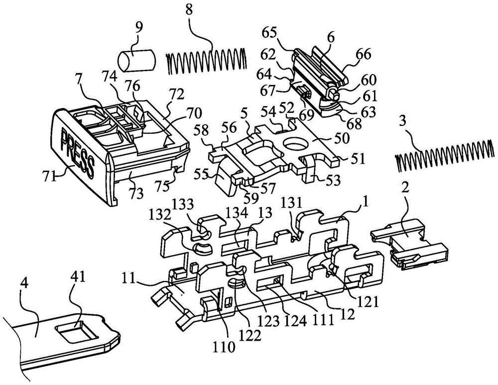
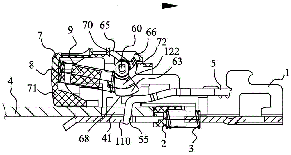
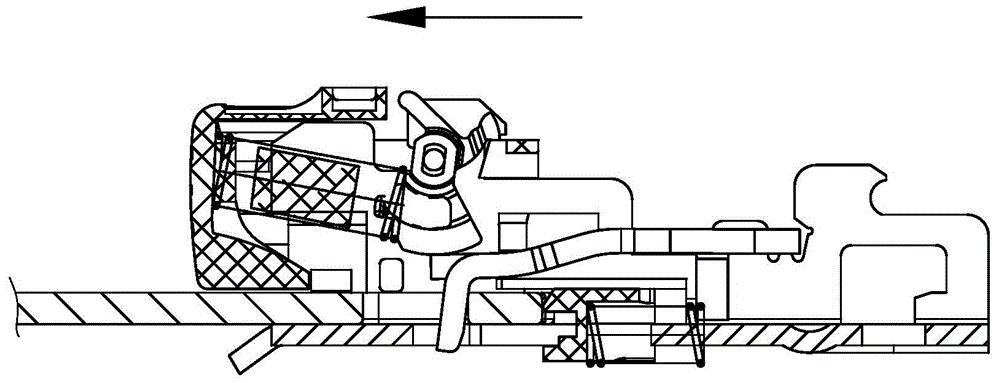
[0033] Up and down, inside and outside in the below refer to image 3 The up and down, inside and outside directions in the picture do not necessarily represent the directions in actual use.

[0034] like Figure 1 to Figure 4 As shown, the buckle device includes a frame 1, a locking plate 5, an inertial locking block 6, a release button 7 and a locking spring 8. The frame 1 is U-shaped and includes a bottom plate 11 and two side walls 12, 13. The bottom plate 11 is connected to Below the two side walls 12 , 13 , the lock tongue 4 is inserted between the two side walls...


PUM


Abstract

The invention provides a belt buckle device. The belt buckle device comprises a framework, a locking plate, an inertial locking block, a releasing button and a locking spring, wherein the inertial locking block is an integrally-molded rotary component provided with a shaft; at a locking position, a part of load on a locking surface is transmitted onto a rotating shaft of the inertial locking block, and the other part of load is transmitted onto a support member through a carrying member. According to the belt buckle device provided by the invention, the inertial locking block is molded integrally, so that molding and assembling processes are simple. During loading, a part of load on the locking surface is transmitted onto the rotating shaft of the inertial locking block, the other part of load is transmitted onto the support member on the framework through the carrying member, and the stress directions of the rotating shaft and the support member point to the axle center of the rotating shaft, so that the locking position is kept stable and is prevented from being deviated, and the spring bolt connection state is stable.

Description

technical field [0001] The invention belongs to the technical field of automobile safety belts, in particular to a belt buckle device. Background technique [0002] As the basic protective device for protecting drivers and occupants during a car collision, the safety belt device is of self-evident importance. Wherein, the belt buckle device is an important part of the safety belt device. [0003] The Chinese patent with notification number CN100593984C discloses a buckle device which is provided with a locking plate which engages with a tongue-shaped plate inserted into the main body of the device and retains the tongue-shaped plate in the main body of the device, and a locking member that engages the locking plate and prevents movement of the locking plate to the release position, and has a body portion and a shaft supporting the body portion within the device body. The main body portion of the locking member is formed of sintered metal and the shaft is formed of metal an...

Claims


Application Information

Patent Timeline
IPC IPC(8): A44B11/25
Inventor 郭剑仁涂俊
Owner BYD CO LTD
Why Eureka
Try Eureka