Connector for mounting electrolytic capacitor onto board and electronic circuit apparatus

a technology for connecting cables and electrolytic capacitors, which is applied in the direction of electrical equipment, connection, coupling device connections, etc., can solve the problems of degrading the mounting efficiency, achieve the effect of improving the mounting efficiency of a circuit on the board, reducing the size of the board, and stable connection state of the electrolytic capacitor

Inactive Publication Date: 2014-11-18
JAPAN AVIATION ELECTRONICS IND LTD
View PDF14 Cites 4 Cited by
  • Summary
  • Abstract
  • Description
  • Claims
  • Application Information

AI Technical Summary

Benefits of technology

[0013]According to the present invention, a body portion of the electrolytic capacitor and the lead wire are held and fixed by the holder and the holder is fitted and attached to the board connector. Therefore, stress due to vibration does not reach the lead and the connecting portion thereof. Thus, it is possible to obtain a stable connection state of the electrolytic capacitor with the board.
[0014]According to the present invention, the holder can be fitted and connected to the board connector in the state where the electrolytic capacitor held by the holder is arranged transversely in a floating state above a circuit element mounting portion. Therefore, mounting efficiency of a circuit on the board is improved as compared with the case where the electrolytic capacitor is directly connected onto the board. Accordingly, it is possible to achieve reduction in size of the board and reduction in size of the electronic circuit apparatus.
[0015]Thus, according to the present invention, it is possible to provide an electronic circuit apparatus in which mounting efficiency and connection stability of an electrolytic capacitor are compatible.
[0016]According to the present invention, the electrolytic capacitor is held by the holder and fitted and attached to the board connector. With this structure, the electrolytic capacitor is easily replaced in case of occurrence of failure in the electrolytic capacitor or the like, as compared with the case where the electrolytic capacitor is directly mounted.
[0017]According to the present invention, the holder fitting portion of the board connector may be arranged to face an opening portion of the case so that the holder can be fitted and attached from the outside of the case. Therefore, the capacitor can easily be replaced from the outside of the case without disassembling the case.
[0018]According to the present invention, the board connector and an input / output connector can be integrally formed. Therefore, it is possible to easily repair the capacitor from the outside of the case without disassembling the case.

Problems solved by technology

Accordingly, when the electrolytic capacitor is directly mounted to the board, mounting efficiency is degraded.

Method used


Image

  • Connector for mounting electrolytic capacitor onto board and electronic circuit apparatus
  • Connector for mounting electrolytic capacitor onto board and electronic circuit apparatus
  • Connector for mounting electrolytic capacitor onto board and electronic circuit apparatus

Examples


first embodiment

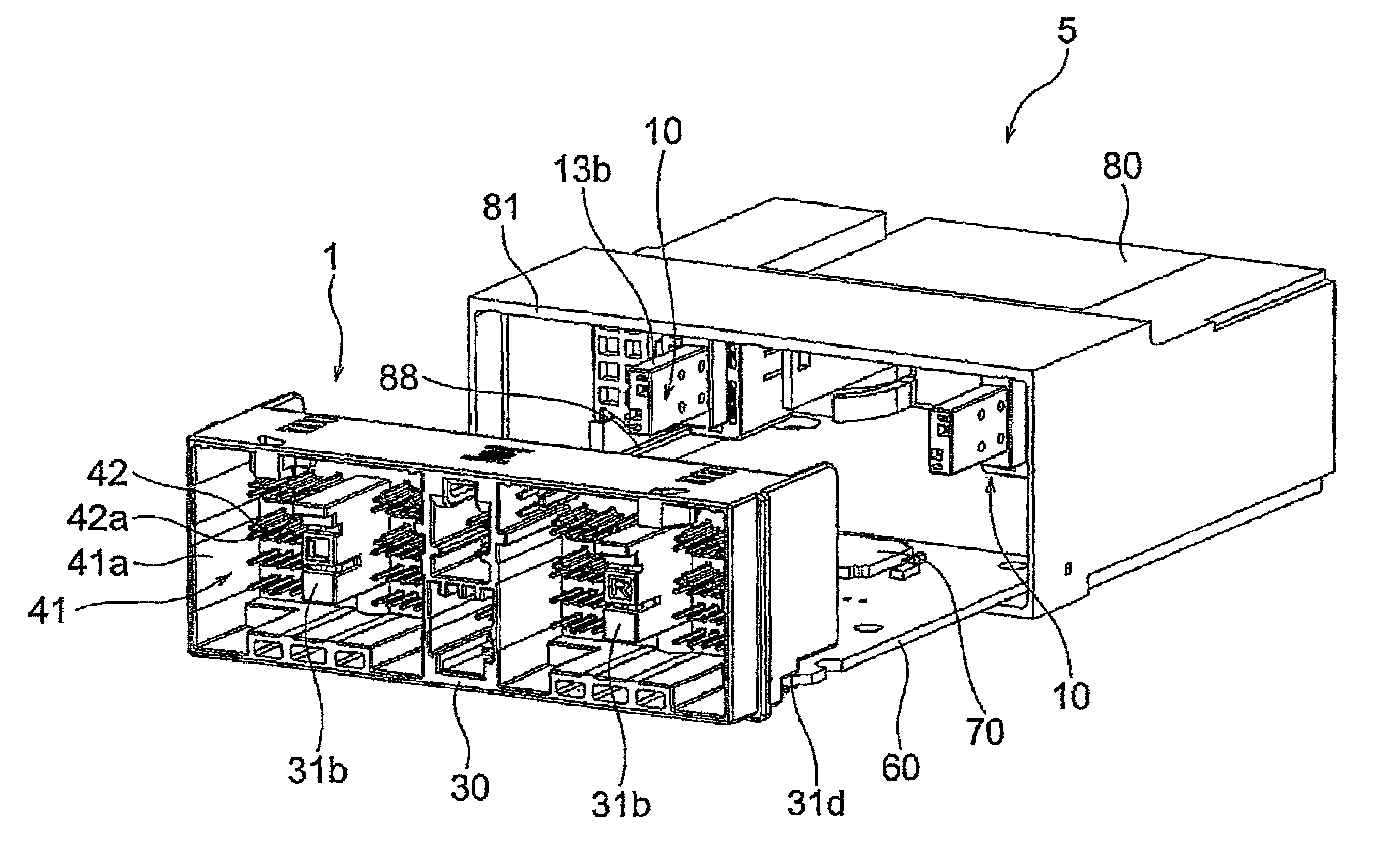
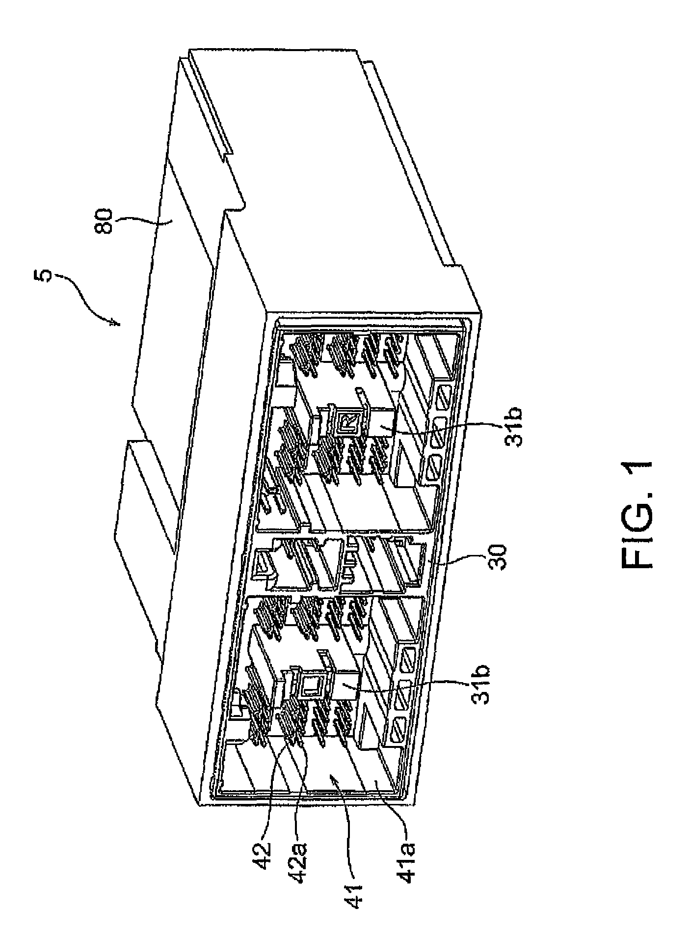
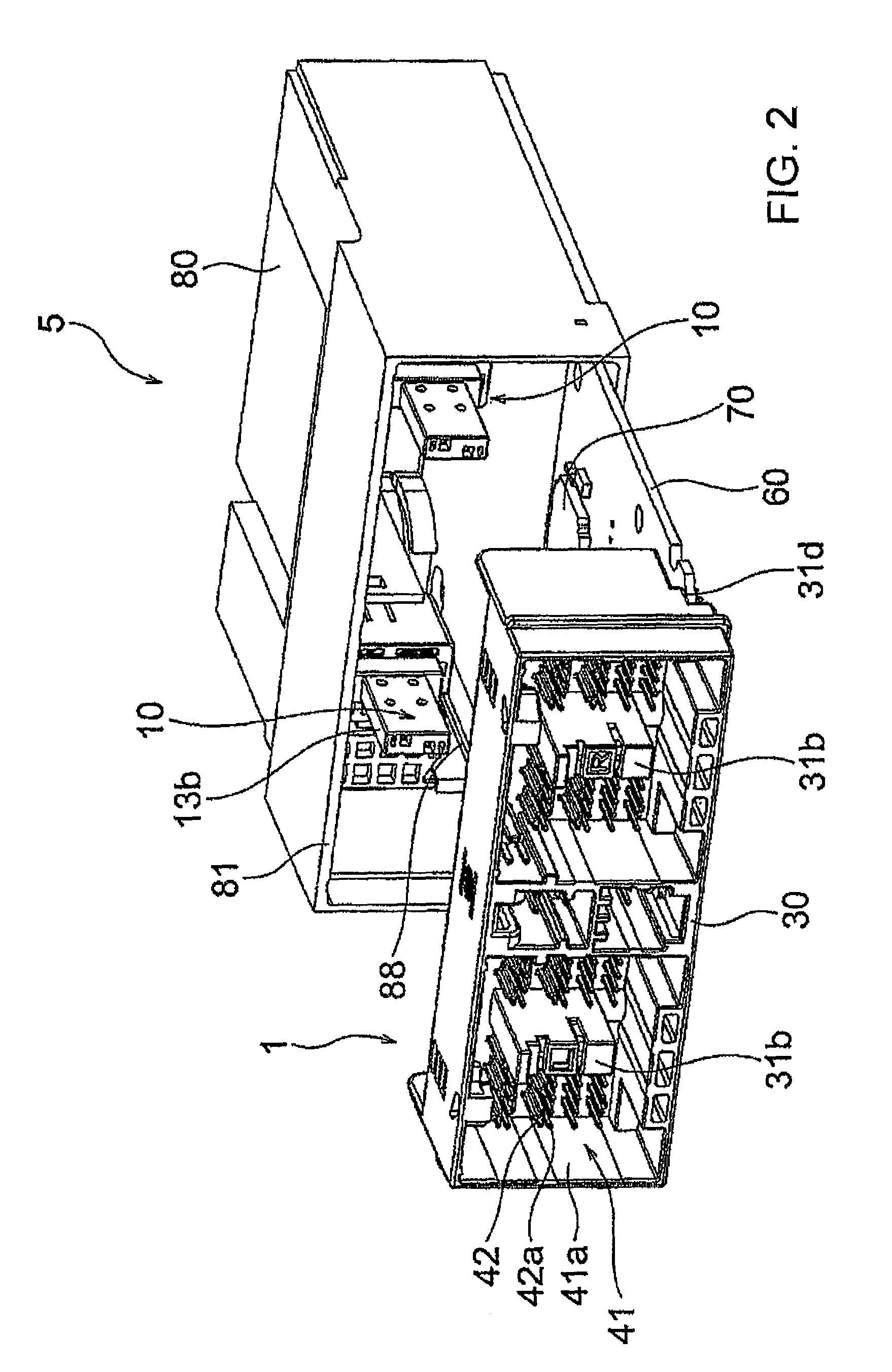
[0049]At first, referring to FIGS. 1 to 15, description will be made about the structure of an electronic circuit apparatus 5 mounted with a board mount connector 1, according to the present invention, for mounting an electrolytic capacitor onto a board.

[0050]Herein, as the electronic circuit apparatus 5, an ECU of an airbag for automobile use is shown by way of example but the present invention is not limited thereto.

[0051]As illustrated in FIGS. 1 to 3, the electronic circuit apparatus 5 comprises a board 60 with circuit elements 70 mounted thereto, a case 80 holding and surrounding the board 60, and the board mount connector 1 (connector for mounting the electrolytic capacitor onto the board) mounted to the board 60 and holding electrolytic capacitors 20. The board mount connector 1 comprises a board connector 30 to be mounted to the board 60 and holders 10 as insulating holding members connected to the board connector 30 and adapted to hold the electrolytic capacitors 20. By mou...

second embodiment

[0109]Next, referring to FIGS. 16 to 28, description will be made about a structure of a board mount connector 1′ according to a

[0110]The board mount connector 1′ according to the second embodiment is similar in structure to the first embodiment. However, in the first embodiment, the holder 10 is fitted and attached to the board connector 30 from its rear side while, in the second embodiment, a holder 10′ is fitted and attached to a board connector 30′ from its front side.

[0111]At first, referring to FIGS. 16 and 17, description will be made about a structure of an electronic circuit apparatus 5′ mounted with the board mount connector 1′, according to the second embodiment of the present invention, for mounting an electrolytic capacitor to a board.

[0112]As illustrated in FIGS. 16 and 17, the electronic circuit apparatus 5′ comprises a board 60′ with circuit elements 70′ mounted thereto, a case 80′ holding and surrounding the board 60′, and the board mount connector 1′ mounted to the...


PUM


Abstract

It is an object of the present invention to provide an electronic circuit apparatus in which mounting efficiency and connection stability of an electrolytic capacitor are compatible. An electronic circuit apparatus 5 of the present invention includes a board 60 with a circuit element 70 mounted thereto, a case 80 holding and surrounding the board 60, and a board mount connector (connector for mounting the electrolytic capacitor onto the board) 1 mounted onto the board 60 and holding the electrolytic capacitor 20. The board mount connector 1 includes a board connector 30 to be mounted onto the board and a holder 10 connected to the board connector 30 and holding the electrolytic capacitor 20 as an insulating holding body. The electrolytic capacitor 20 is mounted onto the board 60 via the board mount connector 1 by mounting the board connector 30 onto the board 60.

Description

CROSS REFERENCE TO RELATED APPLICATIONS[0001]This application is the National Stage of PCT / JP2010 / 068595 filed on Oct. 21, 2010, which claims priority under 35 U.S.C. §119 of Japanese Application No. JP 2009-265956 filed on Nov. 24, 2009, the disclosure of which is incorporated by reference. The international application under PCT article 21(2) was not published in English.TECHNICAL FIELD[0002]The present invention relates to a connector for mounting an electrolytic capacitor onto a board and an electronic circuit apparatus.BACKGROUND ART[0003]In an electronic circuit apparatus in which a board mounted with circuit elements is covered with a case at its periphery, in case where an electrolytic capacitor is used as a circuit element, for example, such as in an ECU (electronic control unit) of an airbag for automobile use, the electrolytic capacitor is often larger in external size as compared with other circuit elements. Accordingly, when the electrolytic capacitor is directly mounte...

Claims


Application Information

Patent Timeline
Patent Type & Authority Patents(United States)
IPC IPC(8): H01R13/66H01R12/72
CPCH01R12/724H01R13/6625
Inventor HAMAOKA, YUJIOHNO, AKIRA
Owner JAPAN AVIATION ELECTRONICS IND LTD
Why Eureka
Try Eureka