Connector for mounting electrolytic capacitor onto board and electronic circuit apparatus
Inactive Publication Date: 2012-09-20
JAPAN AVIATION ELECTRONICS IND LTD
View PDF4 Cites 5 Cited by
Summary
Abstract
Description
Claims
Application Information
AI Technical Summary
This helps you quickly interpret patents by identifying the three key elements:
Problems solved by technology
Method used
Benefits of technology
Benefits of technology
[0013]According to the present invention, a body portion of the electrolytic capacitor and the lead wire are held and fixed by the holder and the holder is fitted and attached to the board connector. Therefore, stress due to vibration does not reach the lead and the connecting portion thereof. Thus, it is possible to obtain a stable connection state of the electrolytic capacitor with the board.
[0014]According to the present invention, the holder can be fitted and connected to the board connector in the state where the electrolytic capacitor held by the holder is arranged transversely in a floating state above a circuit element mounting portion. Therefore, mounting efficiency of a circuit on the board is improved as compared with the case where the electrolytic capacitor is directly connected onto the board. Accordingly, it is possible to achieve reduction in size of the board and reduction in size of the electronic circuit apparatus.
[0015]Thus, according to the present invention, it is possible to provide an electronic circuit apparatus in which mounting efficiency and connection stability of an electrolytic capacitor are compatible.
[0016]According to the present invention, the electrolytic capacitor is held by the holder and fitted and attached to the board connector. With this structure, the electrolytic capacitor is easily replaced in case of occurrence of failure in the electrolytic capacitor or the like, as compared with the case where the electrolytic capacitor is directly mounted.
[0017]According to the present invention, the holder fitting portion of the board connector may be arranged to face an opening portion of the case so that the holder can be fitted and attached from the outside of the case. Therefore, the capacitor can easily be replaced from the outside of the case without disassembling the case.
[0018]According to the present invention, the board connector and an input / output connector can be integrally formed. Therefore, it is possible to easily repair the capacitor from the outside of the case without disassembling the case.
Problems solved by technology
Accordingly, when the electrolytic capacitor is directly mounted to the board, mounting efficiency is degraded.
Method used
Image
Click on the blue label to locate the original text in one second.
Reading with bidirectional positioning of images and text.
Examples
first embodiment
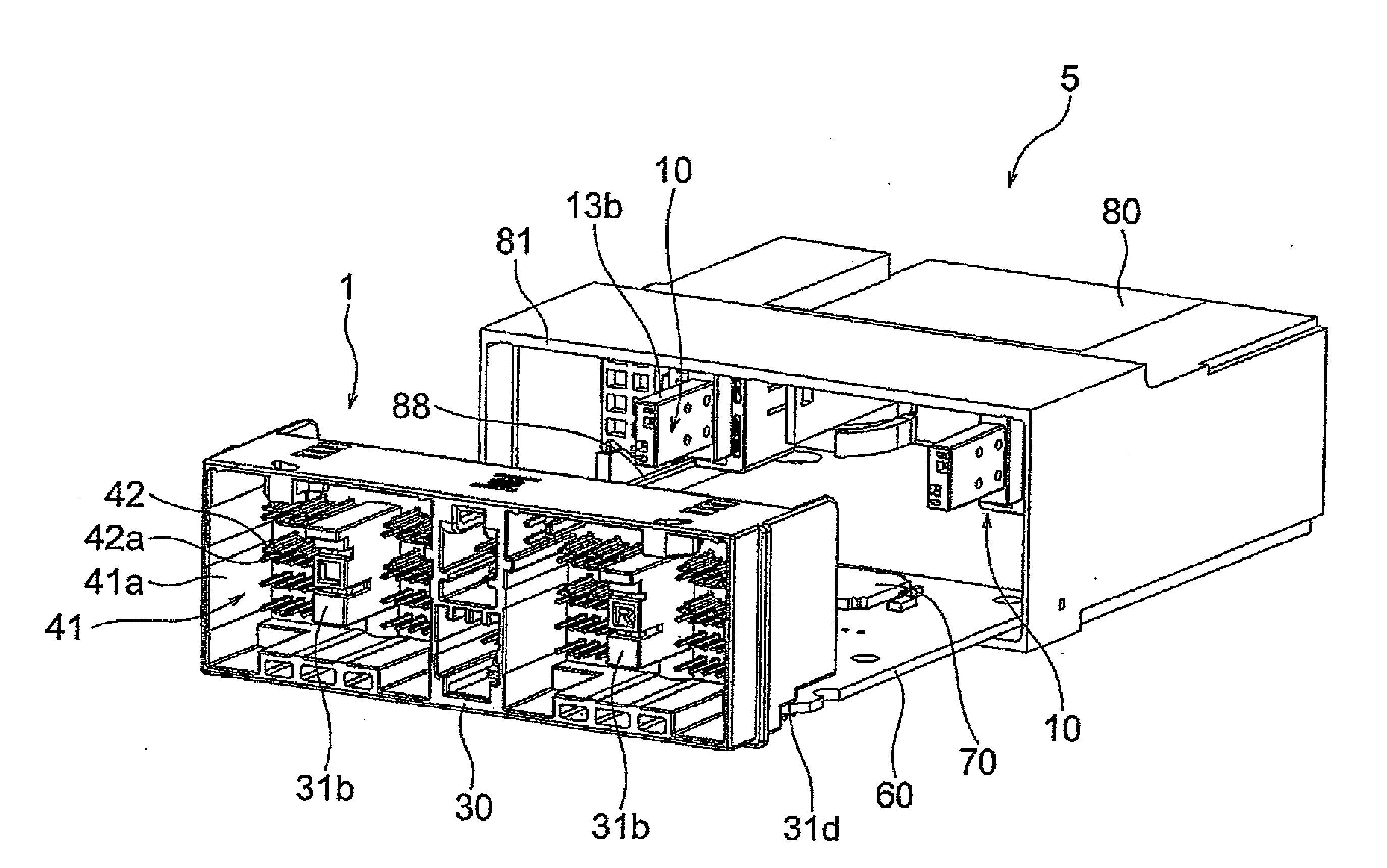
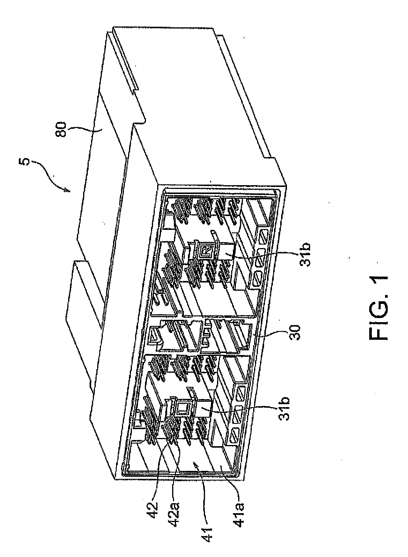
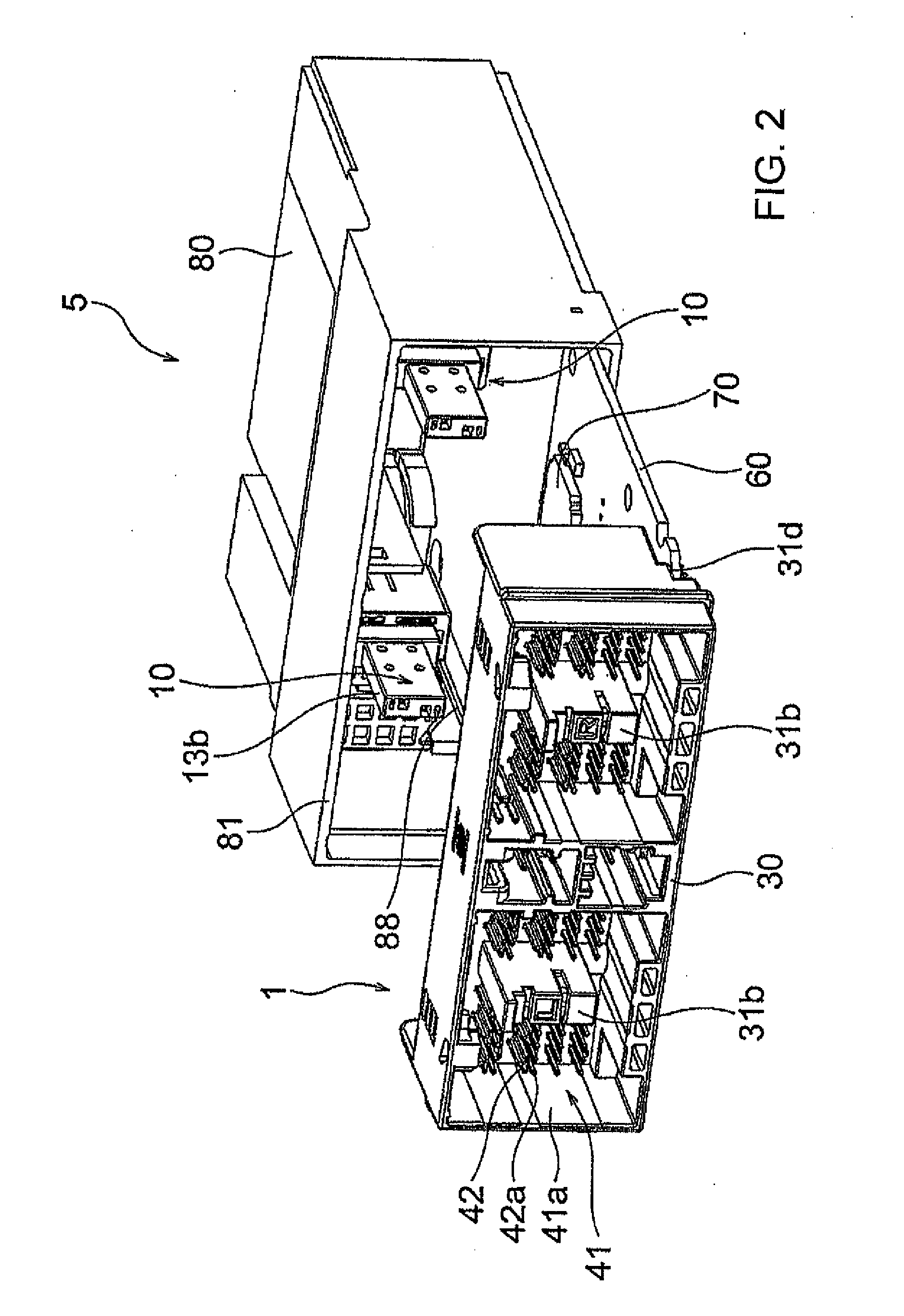
[0049]At first, referring to FIGS. 1 to 15, description will be made about the structure of an electronic circuit apparatus 5 mounted with a board mount connector 1, according to the present invention, for mounting an electrolytic capacitor onto a board.
[0050]Herein, as the electronic circuit apparatus 5, an ECU of an airbag for automobile use is shown by way of example but the present invention is not limited thereto.
[0051]As illustrated in FIGS. 1 to 3, the electronic circuit apparatus 5 comprises a board 60 with circuit elements 70 mounted thereto, a case 80 holding and surrounding the board 60, and the board mount connector 1 (connector for mounting the electrolytic capacitor onto the board) mounted to the board 60 and holding electrolytic capacitors 20. The board mount connector 1 comprises a board connector 30 to be mounted to the board 60 and holders 10 as insulating holding members connected to the board connector 30 and adapted to hold the electrolytic capacitors 20. By mou...
second embodiment
[0109]Next, referring to FIGS. 16 to 28, description will be made about a structure of a board mount connector 1′ according to a
[0110]The board mount connector 1′ according to the second embodiment is similar in structure to the first embodiment. However, in the first embodiment, the holder 10 is fitted and attached to the board connector 30 from its rear side while, in the second embodiment, a holder 10′ is fitted and attached to a board connector 30′ from its front side.
[0111]At first, referring to FIGS. 16 and 17, description will be made about a structure of an electronic circuit apparatus 5′ mounted with the board mount connector 1′, according to the second embodiment of the present invention, for mounting an electrolytic capacitor to a board.
[0112]As illustrated in FIGS. 16 and 17, the electronic circuit apparatus 5′ comprises a board 60′ with circuit elements 70′ mounted thereto, a case 80′ holding and surrounding the board 60′, and the board mount connector 1′ mounted to the...
PUM
Abstract
It is an object of the present invention to provide an electronic circuit apparatus in which mounting efficiency and connection stability of an electrolytic capacitor are compatible. An electronic circuit apparatus 5 of the present invention includes a board 60 with a circuit element 70 mounted thereto, a case 80 holding and surrounding the board 60, and a board mount connector (connector for mounting the electrolytic capacitor onto the board) 1 mounted onto the board 60 and holding the electrolytic capacitor 20. The board mount connector 1 includes a board connector 30 to be mounted onto the board and a holder 10 connected to the board connector 30 and holding the electrolytic capacitor 20 as an insulating holding body. The electrolytic capacitor 20 is mounted onto the board 60 via the board mount connector 1 by mounting the board connector 30 onto the board 60.
Description
TECHNICAL FIELD[0001]The present invention relates to a connector for mounting an electrolytic capacitor onto a board and an electronic circuit apparatus.BACKGROUND ART[0002]In an electronic circuit apparatus in which a board mounted with circuit elements is covered with a case at its periphery, in case where an electrolytic capacitor is used as a circuit element, for example, such as in an ECU (electronic control unit) of an airbag for automobile use, the electrolytic capacitor is often larger in external size as compared with other circuit elements. Accordingly, when the electrolytic capacitor is directly mounted to the board, mounting efficiency is degraded.[0003]Therefore, in order to improve the mounting efficiency, there is a structure in which a body portion (cylindrical portion) of the electrolytic capacitor is mounted in a floating state above the board and arranged transversely so that other circuit elements are mounted under the electrolytic capacitor.[0004]In the above-m...
Claims
Application Information
Patent Timeline
Application Date:The date an application was filed.
Publication Date:The date a patent or application was officially published.
First Publication Date:The earliest publication date of a patent with the same application number.
Issue Date:Publication date of the patent grant document.
PCT Entry Date:The Entry date of PCT National Phase.
Estimated Expiry Date:The statutory expiry date of a patent right according to the Patent Law, and it is the longest term of protection that the patent right can achieve without the termination of the patent right due to other reasons(Term extension factor has been taken into account ).
Invalid Date:Actual expiry date is based on effective date or publication date of legal transaction data of invalid patent.

