

Wearable pupil light reflex measurement equipment
A measurement equipment and light reflection technology, which is applied in the fields of eye testing equipment, medical science, diagnosis, etc., can solve problems such as low light energy utilization rate, weakened light reflection, serious blinking phenomenon, etc., and achieve rich measurement results and high measurement results. Stable, less eye-irritating effect
- Summary
- Abstract
- Description
- Claims
- Application Information
AI Technical Summary
Benefits of technology
Problems solved by technology
Method used
Image

Examples
Embodiment Construction
[0044] The implementation of the present invention will be illustrated by specific specific examples below, and those skilled in the art can easily understand other advantages and effects of the present invention from the contents disclosed in this specification.
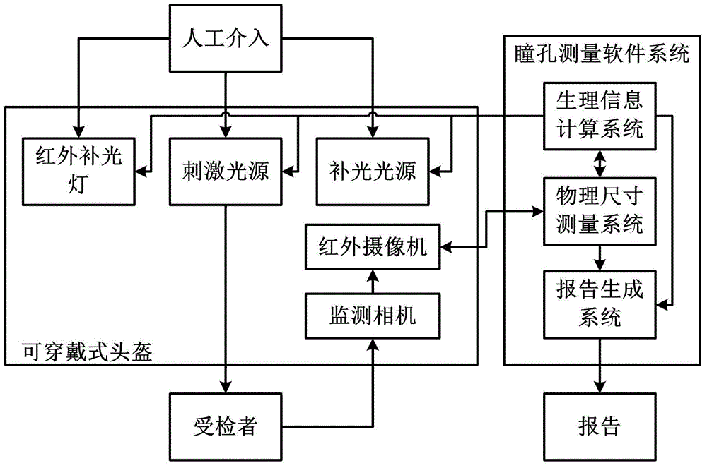
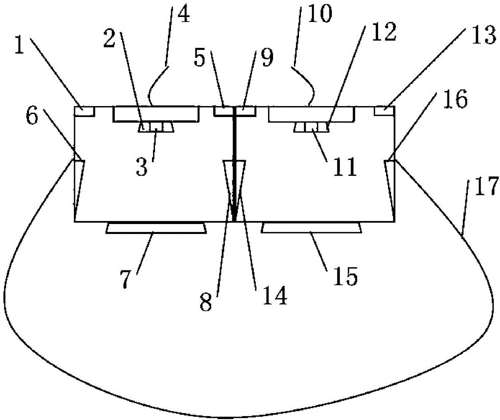
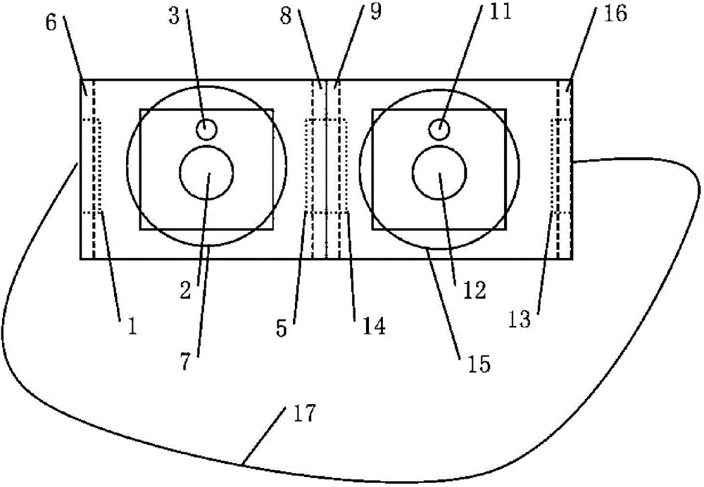
[0045] see Figure 1 to Figure 5 . It should be noted that the structures, proportions, sizes, etc. shown in the drawings attached to this specification are only used to match the content disclosed in the specification, for those who are familiar with this technology to understand and read, and are not used to limit the implementation of the present invention. Limiting conditions, so there is no technical substantive meaning, any modification of structure, change of proportional relationship or adjustment of size, without affecting the effect and purpose of the present invention, should still fall within the scope of the present invention. The disclosed technical content must be within the scope covered. At the sa...
PUM
 Abstract
Description
Claims
Application Information