Iron pipe bending machine with adjustable bending degree

An adjustable and bendable technology, applied in the field of pipe bending machines, can solve the problems such as the inability to adjust the bending degree of the bend, and achieve the effects of convenient height adjustment, simple adjustment operation and saving human resources.

Inactive Publication Date: 2016-08-24
DEYANG KAIDA DOORS
View PDF12 Cites 0 Cited by
  • Summary
  • Abstract
  • Description
  • Claims
  • Application Information

AI Technical Summary

Problems solved by technology

[0004] The technical problem to be solved by the present invention is to provide an iron pipe bending machine with adjustable bending degree, so as to overcome the problem that the existing mechanical bending cannot adjust the bending degree of the bent pipe

Method used


Image

  • Iron pipe bending machine with adjustable bending degree

Examples


Embodiment 1

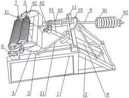
[0021] Such as figure 1 As shown, the iron pipe bending machine with adjustable bending includes a base 1, a fixed frame 2 is arranged on one side of the base 1, and a number of reinforcing bars 21 are arranged on the fixed frame 2, and the two sides on the top of the base 1 The side is provided with a fixed plate 6, the top of the side of the base 1 provided with the fixed frame 2 is provided with a crossbar 11, and the fixed plate 6 is provided with a cylinder I7 with a number of annular spacers on the outer circumference. 1 The two sides of the top are also provided with connecting rods 3, the clamping structure 4 is hinged on the end of the connecting rod 3, the two sides of the clamping structure 4 are provided with clamping plates 42, the clamping plates 42 are hinged with the fixed plate 6, and the clamping Between the plates 42, there is a cylinder II5 that cooperates with the cylinder I7. The annular spacers on the circumferential surface of the cylinder I correspond ...

Embodiment 2

[0024] Such as figure 1 As shown, the iron pipe bending machine with adjustable bending includes a base 1, a fixed frame 2 is arranged on one side of the base 1, and a number of reinforcing bars 21 are arranged on the fixed frame 2, and the two sides on the top of the base 1 The side is provided with a fixed plate 6, the top of the side of the base 1 provided with the fixed frame 2 is provided with a crossbar 11, and the fixed plate 6 is provided with a cylinder I7 with a number of annular spacers on the outer circumference. 1 The two sides of the top are also provided with connecting rods 3, the clamping structure 4 is hinged on the end of the connecting rod 3, the two sides of the clamping structure 4 are provided with clamping plates 42, the clamping plates 42 are hinged with the fixed plate 6, and the clamping Between the plates 42, there is a cylinder II5 that cooperates with the cylinder I7. The annular spacers on the circumferential surface of the cylinder I and the ann...


PUM


Abstract

The invention relates to an iron pipe bending machine with adjustable curvature. The iron pipe bending machine with the adjustable curvature comprises a substrate, a fixed mount is arranged at one side of the substrate, fixed plates are arranged at two sides of the top of the substrate, a cross bar is arranged at the top of the substrate, a column I provided with a plurality of annular division bars on the outer circumferential surface is arranged between the fixed plates, connecting rods are arranged at two sides of the top of the substrate, a clamp structure is hinged to the ends of the connecting rods, clamp plates are arranged at two sides of the clamp structure and hinged to the fixed plates, a column II matched with the column I is arranged between the clamp plates, a hydraulic cylinder is arranged on the fixed mount, the clamp structure is provided with a Y type connecting block, one connecting end of the Y type connecting block is hinged to a hydraulic cylinder, the other connecting end is hinged to a screw rod, the screw rod is through arranged in a fixed plate fixed on the cross bar, and a plurality of limit blocks are arranged at the end of the screw rod. The iron pipe bending machine with the adjustable curvature adjusts the curvature of an elbow through increasing the limit block number, and therefore, the iron pipe bending machine with the adjustable curvature overcomes the problem that the existing mechanical bending cannot adjust the curvature of the elbow.

Description

technical field [0001] The invention relates to the field of pipe bending machines, in particular to an iron pipe bending machine with adjustable bending degree. Background technique [0002] With the development of science and technology and the progress of society, people are constantly pursuing a high-quality living standard and gradually improving their safety awareness. In order to increase the security level, security doors have become an indispensable basic facility in urban housing with many high-rise buildings. The anti-theft door mainly includes the door body and the anti-theft lock set on the door body. During the processing process of the anti-theft door, for the door body that is initially processed, the door body of the anti-theft door is generally made of steel, aluminum or iron. Prepared. For the beauty of the anti-theft door, patterns are generally arranged on the surface of the anti-theft door. The composition of the pattern is generally made of the same ...

Claims


Application Information

Patent Timeline
Patent Type & Authority Patents(China)
IPC IPC(8): B21D7/08B21D7/16
CPCB21D7/08B21D7/16
Inventor 邓洪邓章明
Owner DEYANG KAIDA DOORS
Why Eureka
Try Eureka