
A control valve point riveting machine device for vacuum booster production line

A technology of vacuum booster and production line, which is applied to manufacturing tools, metal processing, metal processing equipment, etc., can solve the problems of poor spot riveting quality, low spot riveting efficiency, difficult spot riveting operation, etc., and achieves high qualification rate and spot riveting. The effect of convenient operation and easy pressing operation

Active Publication Date: 2016-04-06
HANGZHOU WOLEI INTELLIGENT TECH
View PDF7 Cites 0 Cited by
  • Summary
  • Abstract
  • Description
  • Claims
  • Application Information

AI Technical Summary

Problems solved by technology

[0003] The purpose of the present invention is to overcome the disadvantages of point riveting at the control valve of the current vacuum booster production line. The riveting knife is manually operated for point riveting, which has the disadvantages of difficult point riveting operation, low point riveting efficiency and poor point riveting quality, and provides a The control valve point riveting device of the vacuum booster production line with easy point riveting operation, high point riveting efficiency and good point riveting quality

Method used


Image

  • A control valve point riveting machine device for vacuum booster production line
  • A control valve point riveting machine device for vacuum booster production line
  • A control valve point riveting machine device for vacuum booster production line

Examples


Embodiment Construction

[0019] In order to make the above objects, features and advantages of the present invention more comprehensible, the present invention will be further described in detail below in conjunction with the accompanying drawings and specific embodiments.

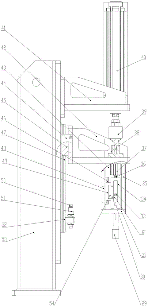
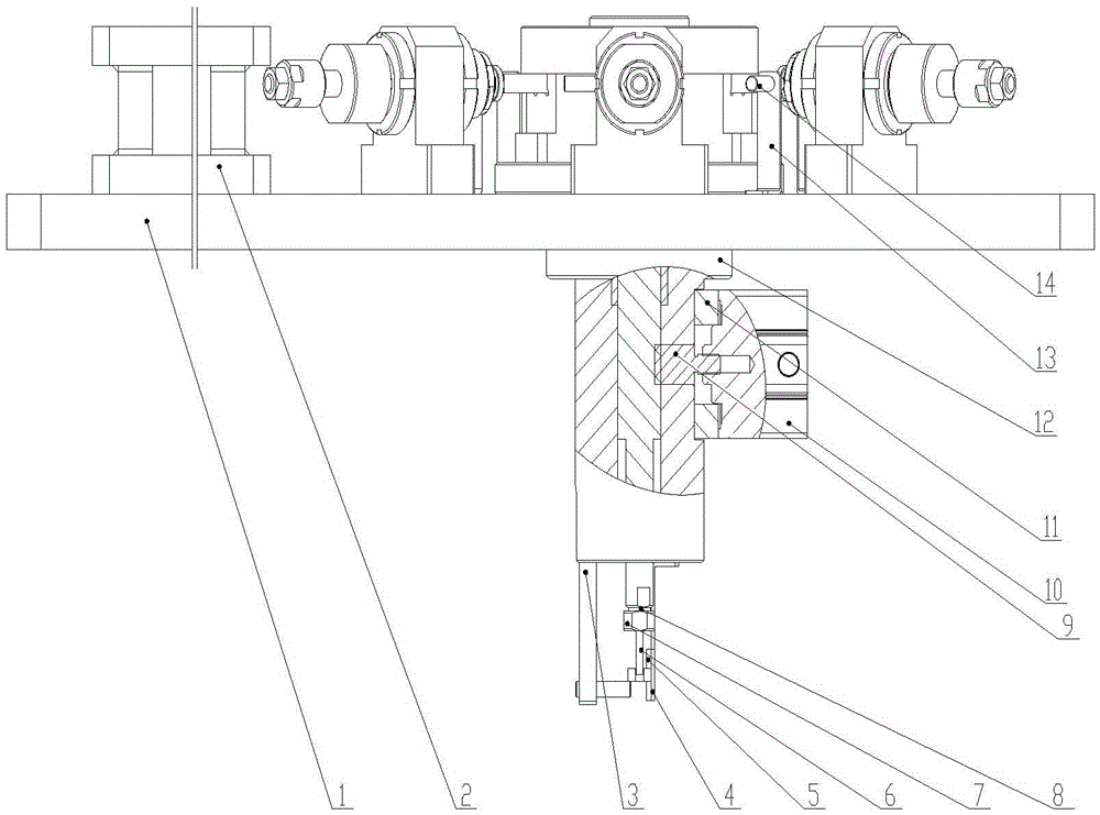
[0020] Reference attached figure 1 , attached figure 2 , a control valve point riveting machine device for a vacuum booster production line of the present invention, including a mounting base plate 1, a column seat 2 fixedly connected to the mounting base plate 1 and a riveting assembly, and a column 53 fixed to the column seat 2 Connected test fixture.

[0021] In this embodiment, the test fixture includes a first linear slide rail 47 connected to the column, a cylinder base 41 and a guide seat 42, the cylinder 40 is located above the cylinder base 41, and the guide base 42 is connected to the first linear slide rail 47 , can slide up and down along the first linear slide rail 47. A joint 38 and a floating joint 39 are respec...


PUM

PropertyMeasurementUnit
diameteraaaaaaaaaa

Abstract

The invention discloses a control valve point special riveting machined device used for a vacuum booster production line. The control valve point special riveting machined device comprises a mounting bottom plate, a stand column and a riveting assembly which are fixedly connected with the mounting bottom plate, and a testing tool which is fixedly connected with the stand column. When the control valve point special riveting machined device used for the vacuum booster production line is used, a shell cover and a shell provided with parts are arranged on the riveting assembly; the riveting assembly is started so that six riveted knives finish the riveting; finally, whether tests finished by the testing tool are qualified or not is judged. The pressing operation is easy, the efficiency is higher and the quality is better.

Description

technical field [0001] The invention relates to the field of vacuum booster assembly, in particular to a control valve point riveting special machine device for a vacuum booster production line. Background technique [0002] The vacuum booster of the car is a key component related to the safety of the car. Its composition includes many parts contained in the upper and lower housings of the booster, such as the sealing ring seat, the sealing ring, the booster diaphragm and the control valve. The riveting diaphragm tray device of the traditional vacuum booster production line has defects such as low riveting efficiency and poor riveting quality. Therefore, a riveting device for the vacuum booster production line with easy riveting operation, high riveting efficiency and good riveting quality is designed. The diaphragm tray device has become an urgent problem to be solved. Contents of the invention [0003] The purpose of the present invention is to overcome the disadvantage...

Claims


Application Information

Patent Timeline
Patent Type & Authority Patents(China)
IPC IPC(8): B23P19/00
CPCB21C51/00B21D39/00
Inventor 陆艺李静伟徐博文郭斌范伟军罗哉胡晓峰
Owner HANGZHOU WOLEI INTELLIGENT TECH
Learn More