
Accelerator operation handle device for engineering machinery

A technology for operating handles and construction machinery, which is applied in the direction of mechanical equipment, engine control, machine/engine, etc. It can solve problems such as loss, safety accidents, touch, pull or other changes, so as to prevent misoperation and improve safety. sexual effect

Inactive Publication Date: 2015-04-29
江苏东俪动力机械制造有限公司
View PDF6 Cites 4 Cited by
  • Summary
  • Abstract
  • Description
  • Claims
  • Application Information

AI Technical Summary

Problems solved by technology

[0002] In the existing engineering machinery, the operator can directly adjust the throttle adjustment part of the throttle operating handle to control the throttle when using the throttle operating handle, no matter in the working state or in the non-working state, which has caused many misoperations. , when the throttle is adjusted in place or does not need to be adjusted, the state of the throttle adjustment part is changed by touching, pulling or other means due to misoperation, resulting in unexpected situations, causing various losses, and even safety accidents

Method used


Image

  • Accelerator operation handle device for engineering machinery
  • Accelerator operation handle device for engineering machinery
  • Accelerator operation handle device for engineering machinery

Examples


Embodiment Construction

[0023] The present invention is described in further detail now in conjunction with accompanying drawing. These drawings are all simplified schematic diagrams, which only illustrate the basic structure of the present invention in a schematic manner, so they only show the configurations related to the present invention.

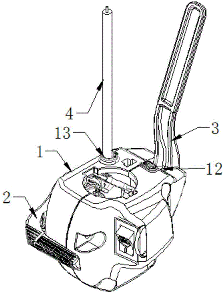
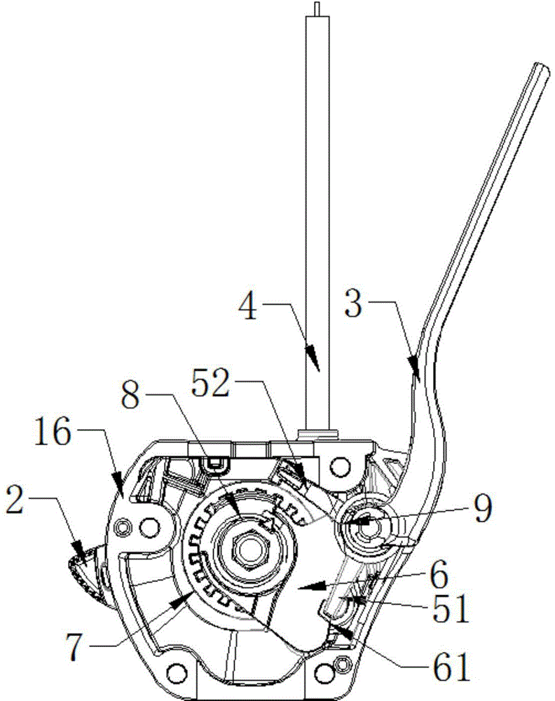
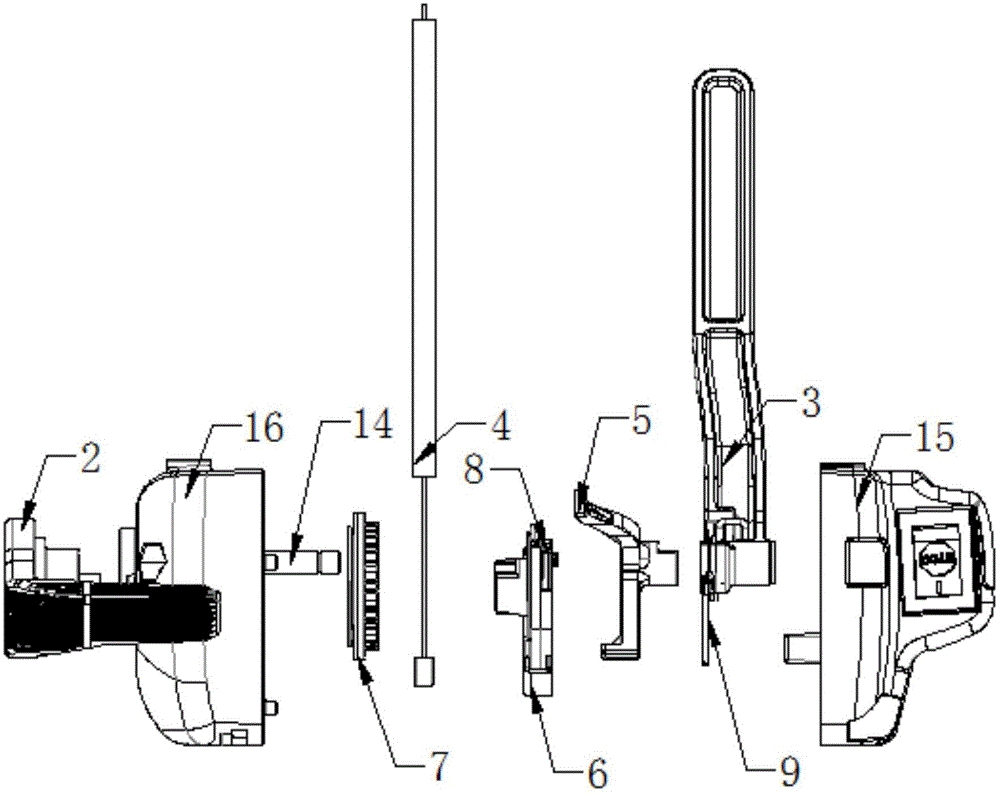
[0024] Such as Figure 1-3 As shown, the present invention is a throttle operating handle device for engineering machinery, including a housing 1, a throttle trigger 2, a handle 3 and a throttle cable 4, the housing 1 is equipped with a claw 5 and a dial 6, the housing 1 Hole one 11, hole two 12 and hole three 13 are provided on the top.

[0025] Such as figure 2 , image 3 and Figure 5 As shown, the throttle trigger 2 is set on the housing 1 through the hole 11, and the throttle trigger 2 can rotate along the hole 11. The throttle trigger 2 has a rotating shaft 2 21 and a shift block 22, and the rotating shaft 2 21 passes through the hole. One 11 protr...


PUM


Abstract

The invention relates to an accelerator operation handle device for engineering machinery. The accelerator operation handle device comprises a shell, an accelerator trigger, a handle and an accelerator line, wherein a clamping claw and a driving plate are arranged in the shell; a hole I, a hole II and a hole III are formed in the shell; the accelerator trigger penetrates through the hole I and sleeves the shell; the driving plate is connected with the accelerator trigger; a bayonet I is formed in the driving plate; a rotating shaft I is fixed on the inner wall of the shell; the handle extends into the shell from the hole II and sleeves the rotating shaft I; the clamping claw is connected with the handle and sleeves the rotating shaft I; the clamping claw is provided with a shifting claw I; the shifting claw I can be clamped into the bayonet I to limit the rotation of the driving plate and the accelerator trigger; the accelerator line penetrates through the hole III and is connected with the driving plate. According to the accelerator operation handle device, the handle is used for controlling the clamping claw to clamp the driving plate, thus limiting the random rotation of the driving plate and the accelerator trigger; before an accelerator is adjusted by the accelerator operation handle device, the handle is required to be driven to start safety protection to prevent mis-operation, so that the safety of the operation on the accelerator operation handle device is improved.

Description

technical field [0001] The invention relates to an accelerator operating handle device for construction machinery, which belongs to the field of construction machinery equipment. Background technique [0002] In the existing engineering machinery, the operator can directly adjust the throttle adjustment part of the throttle operating handle to control the throttle when using the throttle operating handle, no matter in the working state or in the non-working state, which has caused many misoperations. , When the throttle is adjusted in place or does not need to be adjusted, the state of the throttle adjustment part is changed by touching, pulling or other means due to misoperation, resulting in unexpected situations, causing various losses, and even safety accidents. Contents of the invention [0003] The technical problem to be solved by the present invention is to provide an accelerator operating handle device for engineering machinery that can prevent misoperation. [0...

Claims


Application Information

Patent Timeline
IPC IPC(8): F02D11/02F02D11/04
Inventor 耿伟
Owner 江苏东俪动力机械制造有限公司
Learn More