
Fastener and its fan structure

A technology of fixing parts and fans, applied in the direction of friction clamping detachable fasteners, pump components, connecting components, etc., can solve problems such as failures, and achieve the effect of solving failures

Active Publication Date: 2017-07-21
INVENTEC PUDONG TECH CORPOARTION +1
View PDF8 Cites 0 Cited by
  • Summary
  • Abstract
  • Description
  • Claims
  • Application Information

AI Technical Summary

Problems solved by technology

[0004] The technical problem to be solved by the present invention is to provide a fixing part and its fan structure, so as to solve the problem in the prior art that the electronic components in the server are prone to malfunction due to the vibration generated when the fan module is running

Method used


Image

  • Fastener and its fan structure
  • Fastener and its fan structure
  • Fastener and its fan structure

Examples


Embodiment Construction

[0054] Below in conjunction with accompanying drawing, structural principle and working principle of the present invention are specifically described:

[0055] The detailed features and advantages of the present invention are described in detail below in the embodiments, which are sufficient to enable those skilled in the art to understand the technical content of the present invention and implement it accordingly, and according to the contents disclosed in this specification, claims and accompanying drawings, The related objects and advantages of the present invention can be easily understood by anyone skilled in the art. The following examples further illustrate the concept of the present invention in detail, but do not limit the scope of the present invention in any way.

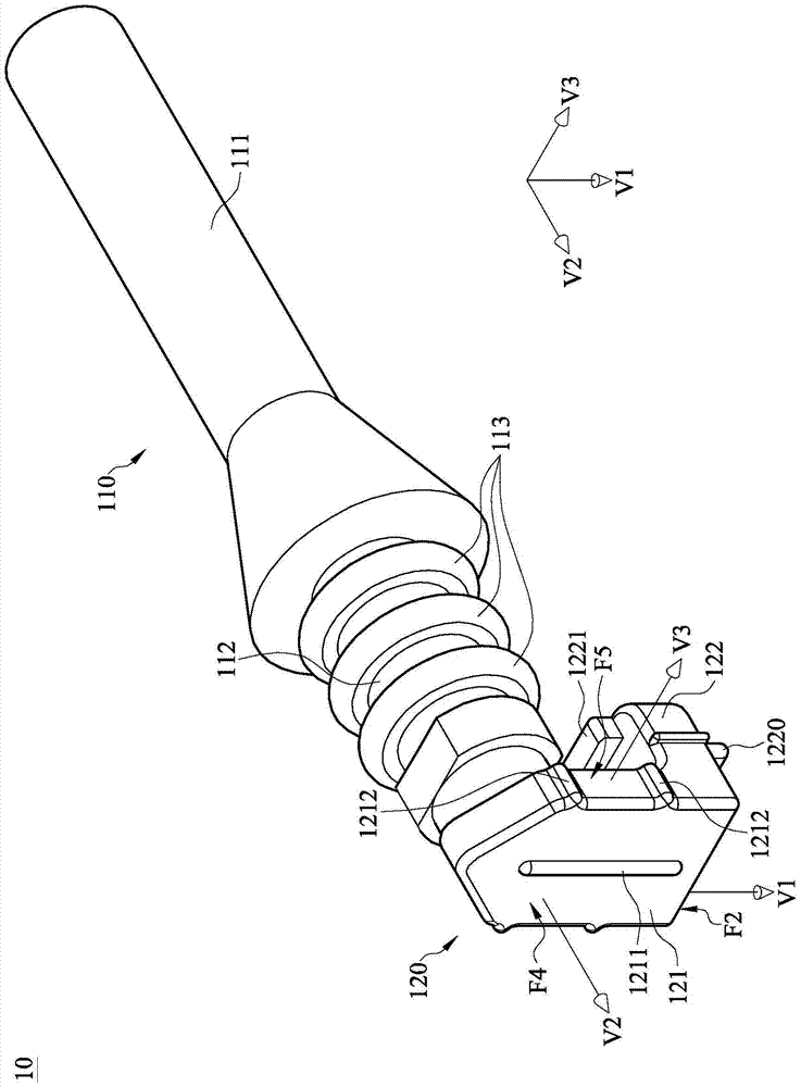
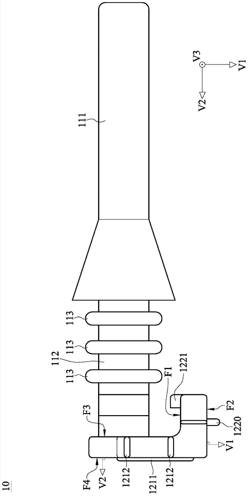
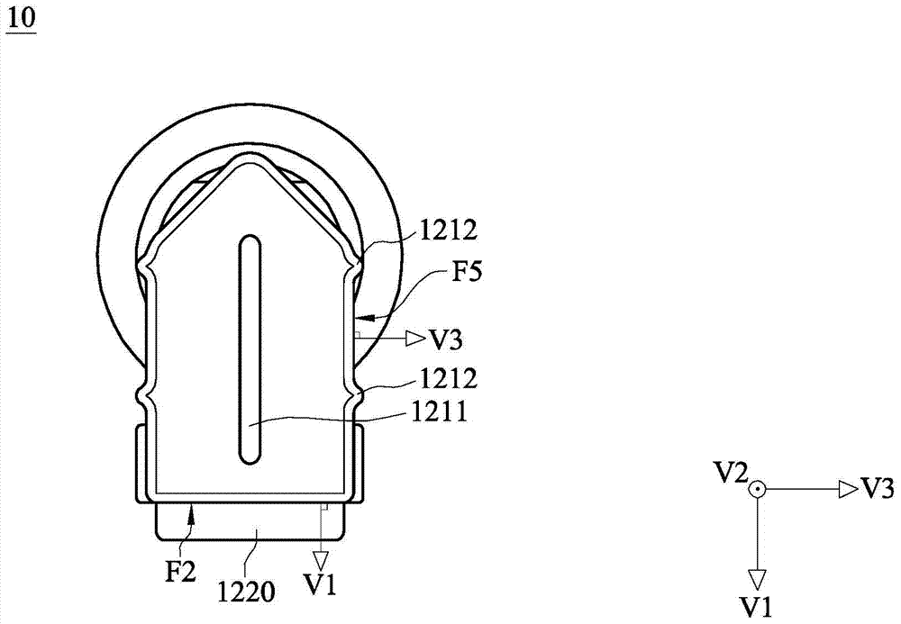
[0056] see Figure 1A to Figure 1C , Figure 1A is a three-dimensional schematic diagram of a fixing member disclosed according to an embodiment of the present invention, Figure 1B for Figure 1A A sch...


PUM


Abstract

A fixing part and its fan structure, the fixing part includes a body and a bending body. The main body includes a piercing part and an extending part connected together. The bending body is connected with the extension part of the main body and includes a first plate body and a second plate body. The first plate body is connected with the extension part. The second board is connected with the first board, and the first board and the second board form an angle. The second plate body has a first surface and a second surface opposite to each other. Face the body first. A first convex rib extends from the second surface. The fan structure includes a frame, at least one fan and a fixing piece. The fixing part passes through the through hole of the frame and the installation hole of the fan so as to fix the fan on the frame. Thereby, the effect of shock isolation is increased.

Description

technical field [0001] The invention relates to a fixing part and its fan structure, in particular to a fixing part and its fan structure with better vibration isolation effect. Background technique [0002] In recent years, with the advancement of science and technology, the operating speed of various electronic components has been continuously improved. For example, the speed of servers has improved dramatically. Along with the increase of the running speed of the server, the heat generation rate of the server is also continuously rising. In order to prevent the server from being overheated, resulting in temporary or permanent failure of the electronic components in the server, it is necessary to install a cooling module in the server to discharge the heat generated by the electronic components out of the server. [0003] For example, installing a fan module in a server is a common cooling method. Specifically, the cooling air is introduced into the server by the fan mo...

Claims


Application Information

Patent Timeline
IPC IPC(8): F04D29/60F04D29/66G06F1/20
CPCF04D29/601F04D29/668G06F1/20F04D19/007F04D25/0613F16B2/22Y10T403/45F16B21/02
Inventor 黄鸿哲吴重谦
Owner INVENTEC PUDONG TECH CORPOARTION
Learn More