Concentric and taper TEM (transverse electromagnetic mode) cell and method for designing interior conductor semi-included angle and exterior conductor semi-included angle of transmission section of concentric and taper TEM cell

A design method and technology of the transmission section, applied in the direction of measuring devices, instruments, measuring electrical variables, etc., can solve problems affecting the quality of the standard field and achieve the effect of improving the performance of the standard field

Inactive Publication Date: 2015-04-29
BEIJING INST OF RADIO METROLOGY & MEASUREMENT
View PDF10 Cites 12 Cited by
  • Summary
  • Abstract
  • Description
  • Claims
  • Application Information

AI Technical Summary

Problems solved by technology

[0006] For the above transmission section structure, the number of high-order modes in the first few order modes i

Method used


Image

  • Concentric and taper TEM (transverse electromagnetic mode) cell and method for designing interior conductor semi-included angle and exterior conductor semi-included angle of transmission section of concentric and taper TEM cell
  • Concentric and taper TEM (transverse electromagnetic mode) cell and method for designing interior conductor semi-included angle and exterior conductor semi-included angle of transmission section of concentric and taper TEM cell
  • Concentric and taper TEM (transverse electromagnetic mode) cell and method for designing interior conductor semi-included angle and exterior conductor semi-included angle of transmission section of concentric and taper TEM cell

Examples


Embodiment Construction

[0043] In order to illustrate the present invention more clearly, the present invention will be further described below in conjunction with preferred embodiments and accompanying drawings. Similar parts in the figures are denoted by the same reference numerals. Those skilled in the art should understand that the content specifically described below is illustrative rather than restrictive, and should not limit the protection scope of the present invention.

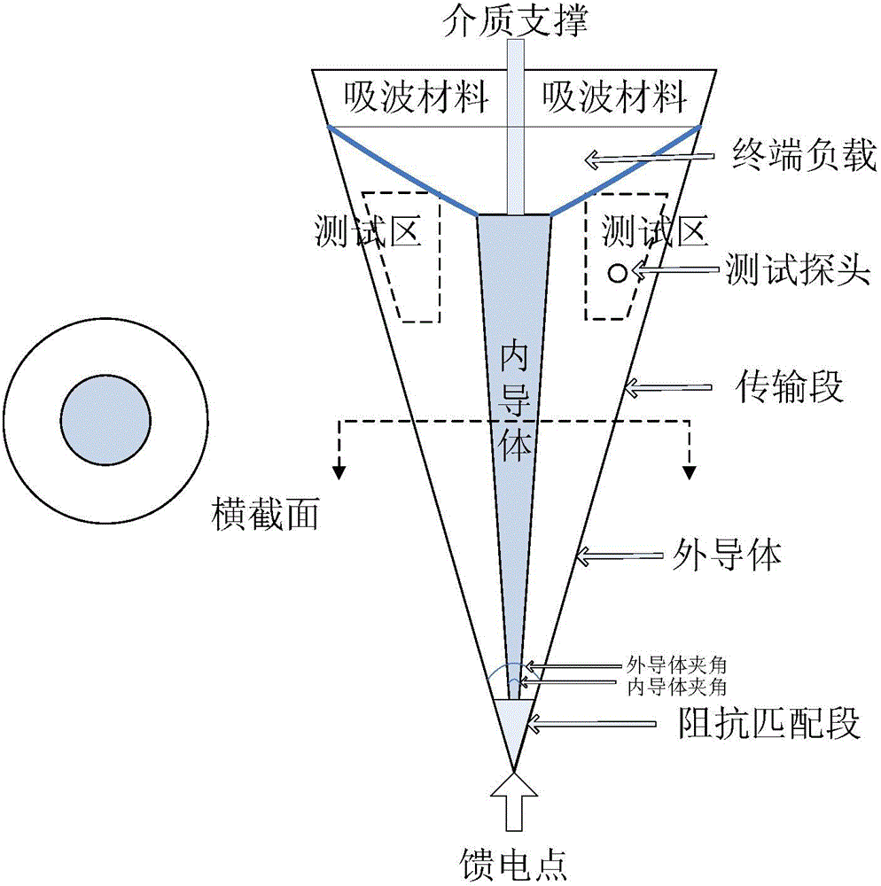
[0044] Such as figure 1 As shown, the structure of the transmission section of the concentric conical TEM chamber adopted in this embodiment is similar to the structure of the transmission section of the concentric conical TEM chamber designed by NIST, but the inner conductor of the coaxial double conductor transmission section of the concentric conical TEM chamber in this embodiment The half included angle is 1.5136° and the half included angle of the outer conductor is 8°, the characteristic impedance ranges from 75Ω to ...


PUM

PropertyMeasurementUnit
Impedanceaaaaaaaaaa

Abstract

The invention discloses a concentric and taper TEM (transverse electromagnetic mode) cell and a method for designing an interior conductor semi-included angle and an exterior conductor semi-included angle of a transmission section of the concentric and taper TEM cell. The method comprises the following steps: according to the use requirement of the transmission section of the concentric and taper TEM cell, characteristic impedance ZC and a ratio theta 2/theta 1 of the exterior conductor semi-included angle and the interior conductor semi-included angle of the transmission section are selected; high order mode quantities corresponding to different interior conductor semi-included angles and exterior conductor semi-included angles of the transmission section of the concentric and taper TEM cell are calculated according to the selected characteristic impedance ZC and the ratio theta 2/theta 1 of the exterior conductor semi-included angle and the interior conductor semi-included angle of the transmission section of the concentric and taper TEM cell, the interior conductor semi-included angle and the exterior conductor semi-included angle which correspond to the minimum high order mode quantity are selected to serve as the interior conductor semi-included angle and the exterior conductor semi-included angle of the transmission section of the concentric and taper TEM cell. With adoption of the technical scheme, the interior conductor semi-included angle and the exterior conductor semi-included angle of the transmission section of the concentric and taper TEM cell are designed, so that the quantity of the high order mode is reduced, the high order mode cut-off frequency is increased, and the performance of the concentric and taper TEM cell is improved.

Description

technical field [0001] The present invention relates to concentric cone type TEM cells. More specifically, it relates to a design method for a concentric conical TEM chamber and the angle between inner and outer conductors of its transmission section. Background technique [0002] The concentric conical TEM chamber is a field strength generating device based on the standard field method. Compared with the TEM chamber and the GTEM chamber, the concentric conical TEM chamber can generate an electromagnetic field with a frequency band of 200MHz to 40GHz, which can be used to establish a broadband field strength calibration system , to meet the full-band, broadband sweep calibration requirements of field strength probes. The concentric cone TEM chamber was first developed by the National Institute of Standards and Technology NIST in 1999. Similar to the coaxial transmission line, it is a double-conductor transmission line with an axisymmetric structure. , terminal load and abs...

Claims


Application Information

Patent Timeline
IPC IPC(8): G01R35/00
Inventor 刘星汛齐万泉穆晨晨马蔚宇黄承祖闫旭红
Owner BEIJING INST OF RADIO METROLOGY & MEASUREMENT
Why Eureka
Try Eureka