Zoom lens
A zoom lens and lens group technology, applied in the field of zoom lenses, can solve problems such as defocus and chromatic aberration, achieve the effect of shortening the total length and realizing a large aperture ratio
- Summary
- Abstract
- Description
- Claims
- Application Information
AI Technical Summary
Problems solved by technology
Method used
Image

Examples
Embodiment 1
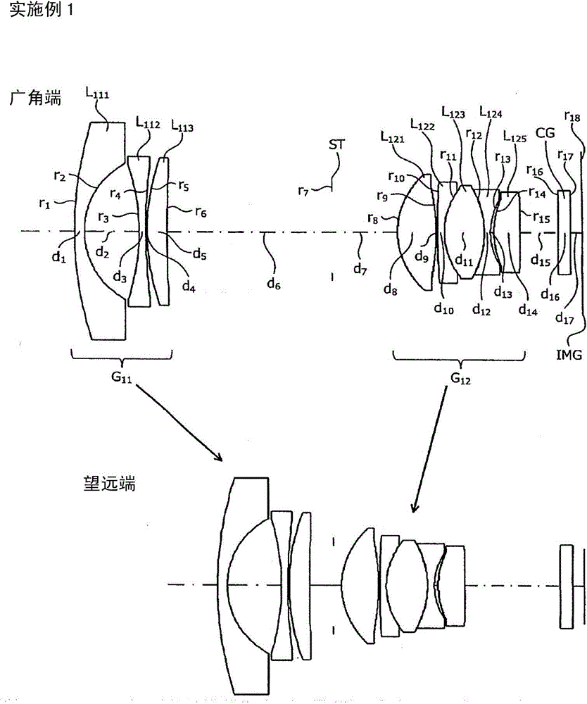
[0083] figure 1 It is a sectional view along the optical axis showing the structure of the zoom lens according to the first embodiment. In this zoom lens, the first lens group G having negative refractive power is sequentially arranged on the object side not shown in the figure. 11 , an aperture stop ST that specifies a predetermined aperture, and a second lens group G with positive refractive power 12 . In the second lens group G 12 A cover glass CG is disposed between the imaging surface IMG and the imaging plane IMG. The cover glass CG is a member arranged as needed, and can be omitted when unnecessary. Furthermore, a light receiving surface of an imaging element such as a CCD or a CMOS is disposed on the imaging surface IMG.
[0084] The first lens group G 11 Negative lens L arranged in order from the object side 111 , negative lens L 112 , and positive lens L 113 made. Negative lens L 111 Consists of a meniscus lens with the convex surface facing the object sid...
Embodiment 2
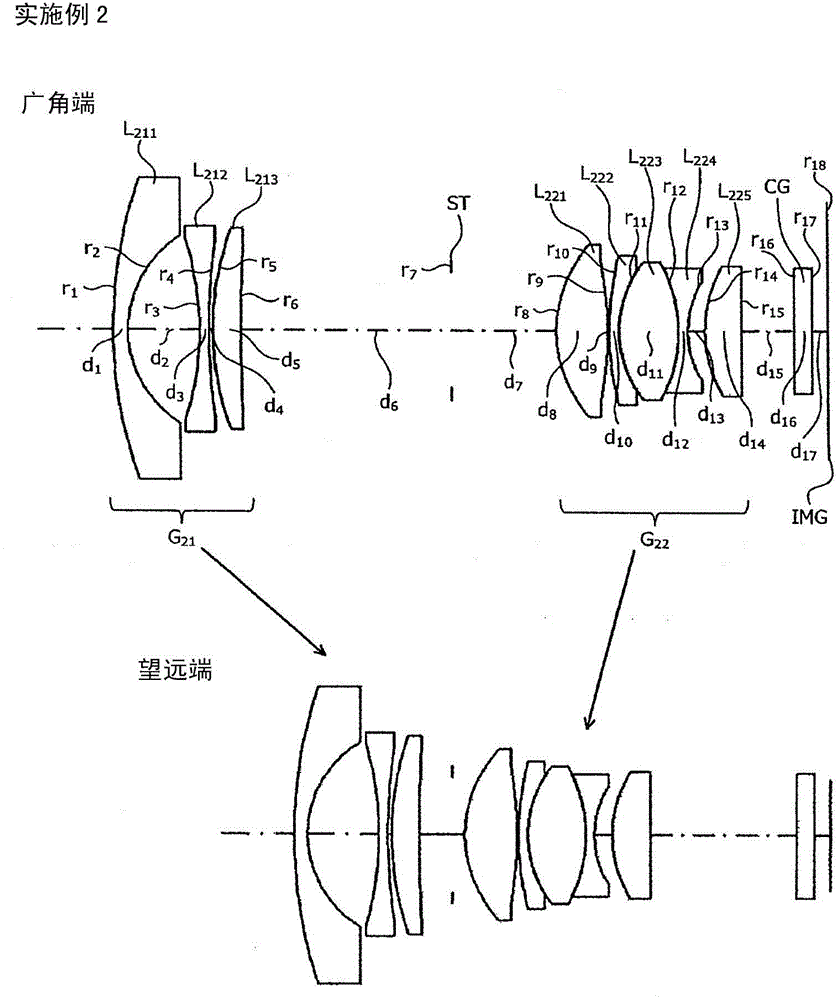
[0164] image 3It is a sectional view along the optical axis showing the structure of the zoom lens according to the second embodiment. The zoom lens is arranged sequentially from the object side not shown, and has a first lens group G having negative refractive power. 21 , an aperture stop ST that specifies a predetermined aperture, and a second lens group G with positive refractive power 22 . In the second lens group G 22 A cover glass CG is disposed between the imaging surface IMG and the imaging plane IMG. The cover glass CG is a member arranged as needed, and can be omitted when unnecessary. Furthermore, a light receiving surface of an imaging element such as a CCD or a CMOS is disposed on the imaging surface IMG.
[0165] The first lens group G 21 Negative lens L arranged in order from the object side 211 , negative lens L 212 , and the positive lens L 213 made. Negative lens L 211 Consists of a meniscus lens with the convex surface facing the object side. Ne...
Embodiment 3
[0245] Figure 5 It is a sectional view along the optical axis showing the structure of the zoom lens according to the third embodiment. The zoom lens is arranged sequentially from the object side not shown, and has a first lens group G having negative refractive power. 31 , an aperture stop ST that specifies a predetermined aperture, and a second lens group G with positive refractive power 32 . In the second lens group G 32 A cover glass CG is disposed between the imaging surface IMG and the imaging plane IMG. The cover glass CG is a member arranged as needed, and can be omitted when unnecessary. Furthermore, a light receiving surface of an imaging element such as a CCD or a CMOS is disposed on the imaging surface IMG.
[0246] The first lens group G 31 Negative lens L arranged in order from the object side 311 , negative lens L 312 , and the positive lens L 313 made. Negative lens L 311 Consists of a meniscus lens with the convex surface facing the object side. N...
PUM
 Abstract
Description
Claims
Application Information
 - R&D Engineer
- R&D Manager
- IP Professional
- Industry Leading Data Capabilities
- Powerful AI technology
- Patent DNA Extraction
Browse by: Latest US Patents, China's latest patents, Technical Efficacy Thesaurus, Application Domain, Technology Topic.
© 2024 PatSnap. All rights reserved.Legal|Privacy policy|Modern Slavery Act Transparency Statement|Sitemap