Plane display panel and display device

A flat-panel display and panel technology, applied in identification devices, nonlinear optics, instruments, etc., can solve problems such as inability to accurately reflect the proportional relationship, difficulty in manufacturing TFT-LCD array substrates, and lack of restoration of object authenticity. To achieve the effect of low cost

Active Publication Date: 2015-04-29
SHANGHAI AVIC OPTOELECTRONICS +1
View PDF6 Cites 48 Cited by
  • Summary
  • Abstract
  • Description
  • Claims
  • Application Information

AI Technical Summary

Problems solved by technology

That is to say, the viewing angles corresponding to the equal-length line segments of ordinary flat-panel displays are not the same, and the lengths perceived by the observers are also different, so that they cannot accurately reflect the proportional relationship between objects on the real screen and affect the authenticity of objects. Th

Method used


Image

  • Plane display panel and display device
  • Plane display panel and display device
  • Plane display panel and display device

Examples


Embodiment Construction

[0024] The following will clearly and completely describe the technical solutions in the embodiments of the present invention with reference to the accompanying drawings in the embodiments of the present invention. Obviously, the described embodiments are only some, not all, embodiments of the present invention. Based on the embodiments of the present invention, all other embodiments obtained by persons of ordinary skill in the art without creative efforts fall within the protection scope of the present invention.

[0025] The shape and size of each device in the drawings do not reflect their true proportions, but are only intended to schematically illustrate the content of the present invention.

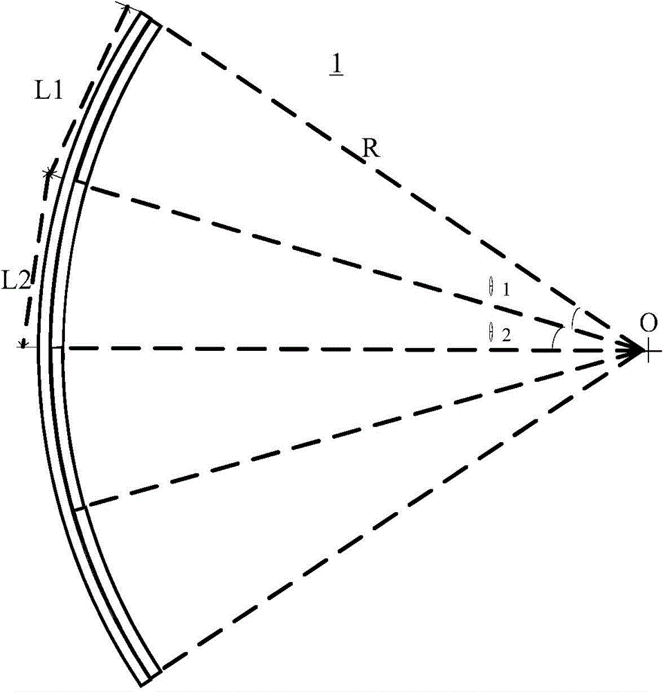
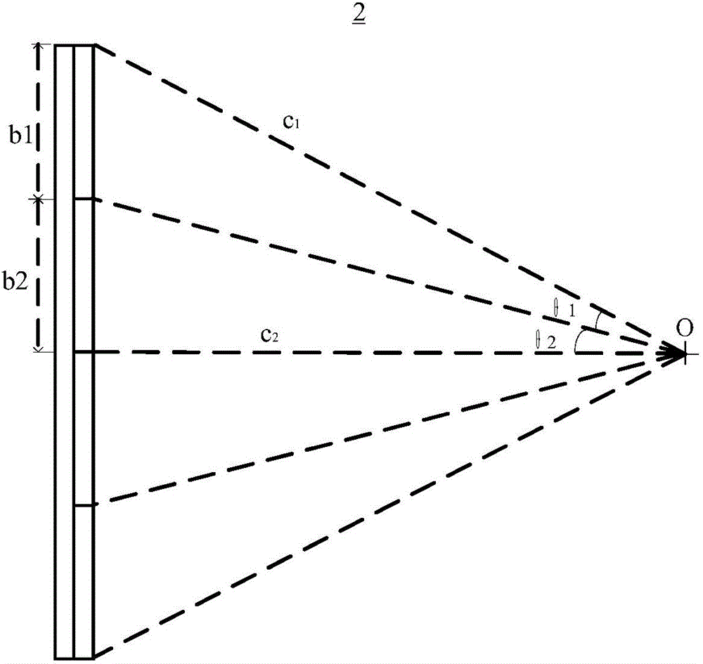
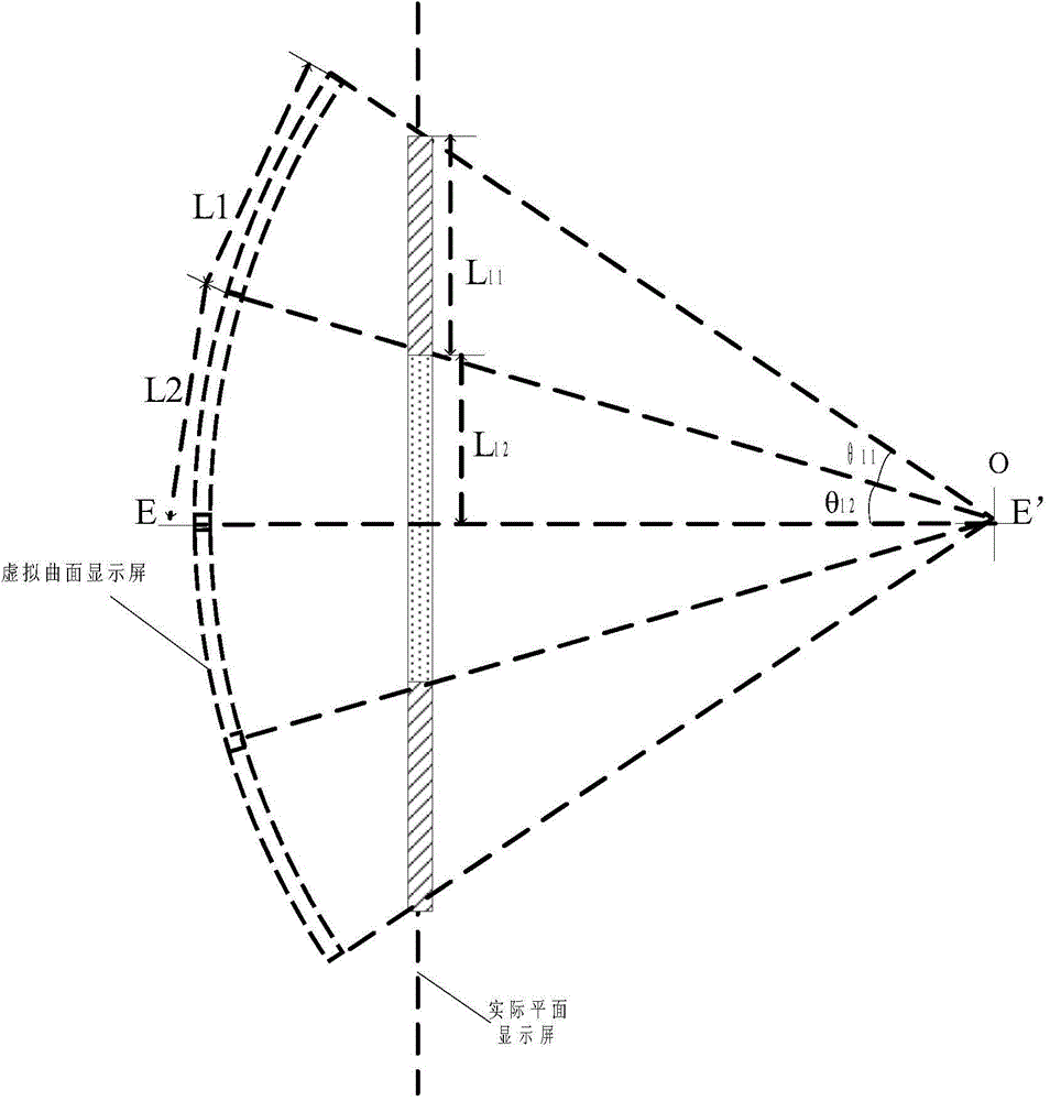
[0026] Such as Figure 3-Figure 4 As shown, in order to realize the display effect of displaying curved surfaces on the flat display panel, the present invention is based on the idea of ​​"projection": to project the line segments of equal arc length onto the flat display screen, so...


PUM


Abstract

The invention discloses a panel display screen with the curved surface display effect, and a display of the plane display screen. According to the plane display panel and the display device, the sub-pixel pitch of a sub-pixel on the display panel is sequentially increased from a central shaft of an effective display area to the periphery, so that the curved surface display effect can be achieved on the plane display.

Description

technical field [0001] The invention relates to the technical field of liquid crystal display, in particular to a flat display panel and a display device with curved surface display effect. Background technique [0002] Curved displays currently on the market, such as curved TVs, are curved display screens. Due to the curved surface of the curved display itself, the distance between each pixel on the screen and the human eye can be equal, and it can more realistically restore the human eye. What a visual experience. For example, at a suitable viewing position, the angle of view of an object per unit length displayed on a curved display is the same, while the object of the same unit length on a flat-panel display has different display positions on the flat-panel display, so that the size of the viewing angle entering the observer is different. Are not the same. [0003] Specifically, as Figure 1-2 shown, where figure 1 is a schematic diagram of a curved display, figure...

Claims


Application Information

Patent Timeline
IPC IPC(8): G09F9/35
CPCG09F9/35G02F1/133512G02F1/134309G02F1/134336G02F1/134345
Inventor 金慧俊
Owner SHANGHAI AVIC OPTOELECTRONICS
Why Eureka
Try Eureka