A Digital Surveying and Mapping Method for Transmission Line Channels

A transmission line and channel technology, which is applied in the direction of electrical digital data processing, surveying and navigation, measuring devices, etc., can solve the problems of inability to realize digital and visual analysis of tree growth threat lines, potential safety hazards of transmission line channels, and low accuracy. , to achieve the effect of improving operation safety, low cost and improving work efficiency

Active Publication Date: 2018-05-22
MAINTENANCE BRANCH STATE GRID LIAONING ELECTRIC POWER +2
View PDF2 Cites 0 Cited by
  • Summary
  • Abstract
  • Description
  • Claims
  • Application Information

AI Technical Summary

Problems solved by technology

[0005] At present, the management of transmission line channels still adopts the method of manual hand drawing and picture collection. The places where there are channel crossings and the distance between trees are checked by manual measurement. The picture data cannot be well correlated with the measurement data and cannot be realized. The digital and visual analysis of the threat of tree growth to line safety will cause potential safety hazards in transmission line channels, and in severe cases will cause line trips
At the same time, the core tree method of transmission lines uses methods such as manual visual inspection, instrument measurement, tower visual inspection, and manual routing. The authenticity of tree measurement data is affected by many factors such as angle, instrument accuracy, and weather, and the accuracy is not high; at the same time These measurement processes also have the problems of high work intensity and high potential safety hazards.

Method used


Image

  • A Digital Surveying and Mapping Method for Transmission Line Channels
  • A Digital Surveying and Mapping Method for Transmission Line Channels
  • A Digital Surveying and Mapping Method for Transmission Line Channels

Examples


Embodiment Construction

[0024] The specific embodiment of the present invention will be further described below in conjunction with accompanying drawing:

[0025] A method for digital surveying and mapping of transmission line channels according to the present invention includes aerial survey digital surveying, computer three-dimensional mapping and graphic output process; including the following steps:

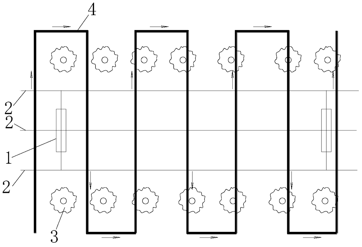
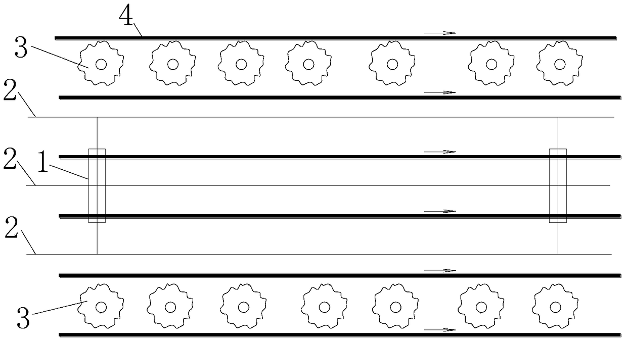
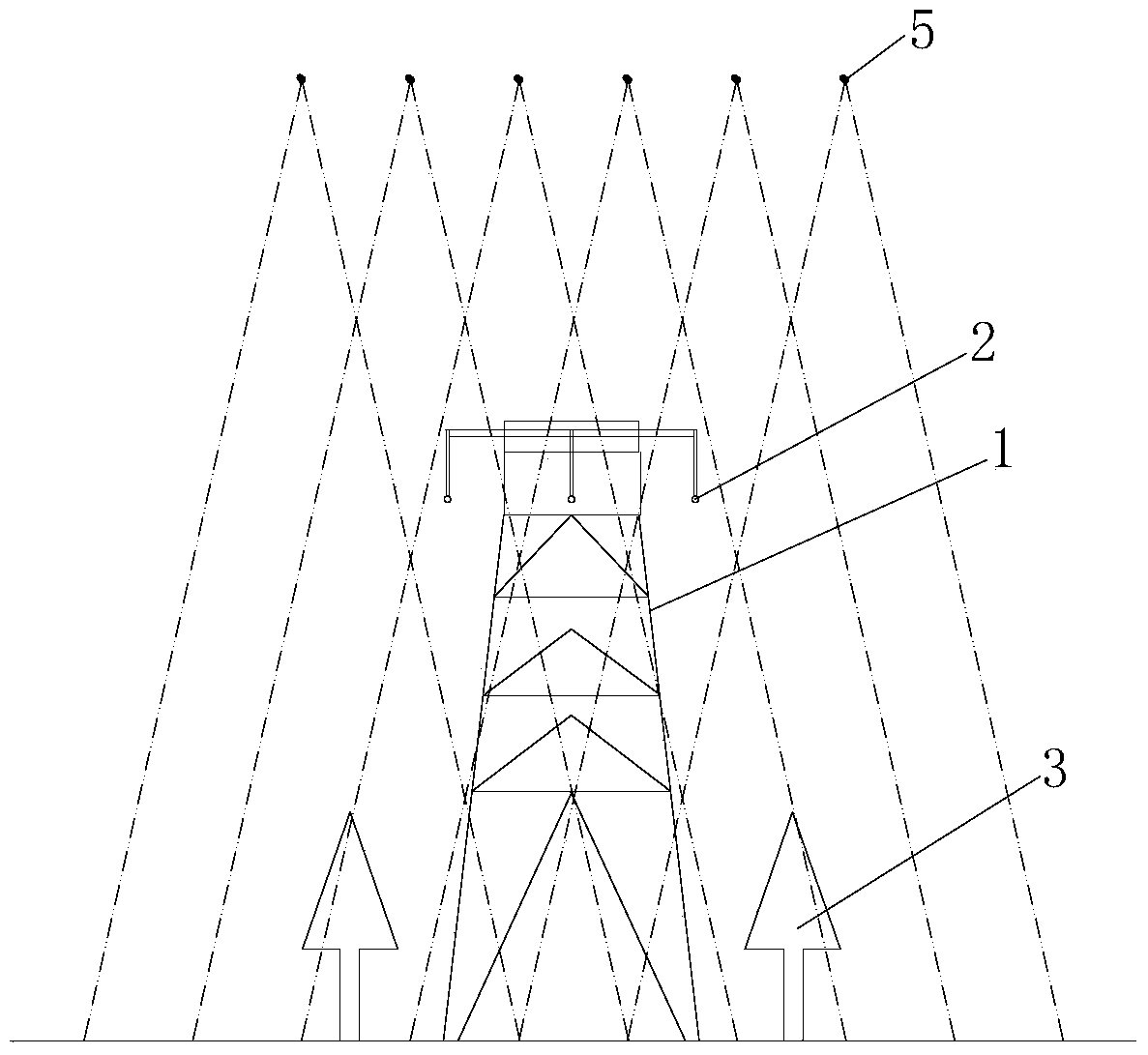
[0026] 1) Aerial photography, install a fully automatic digital aerial survey camera 5 on the UAV, take aerial photography at a height of 10 to 50 meters above the transmission line 2 channel, and set the interval as a standard within the overlapping range of the two shooting angles of an object of 1 cm The shooting time, and ensure that the overlapping range of the two captured pictures along the line is more than 75%, and the upper and lower overlapping ranges are more than 60%; (such as image 3 shown)

[0027] 2) The full-automatic digital aerial survey camera 5 is connected with the GPS to syn...


PUM


Abstract

The invention relates to a power transmission line channel digital surveying method. The method comprises the following steps: 1)taking aerial photographs: taking aerial photographs at the 10-50m height above the power transmission line channel; 2) connecting a full-automatic digital aerial-survey camera with a GPS, synchronously acquiring geographical information data in a flight range and flight status data of an unmanned plane; 3) selecting an obvious ground feature point on a photo as a photo control point to acquire a plane position and elevation of the photo control point; 4) drawing a three-dimensional ground feature model and a landform model along the power transmission line channel; 5) making a three-dimensional survey map, and annotating, editing, storing or outputting the map. The unmanned plane aerial surveying is used for performing digital image acquisition on the power transmission line channel, and the acquired image with a geographical coordinate position is converted into three-dimensional digital image data through the adoption of visual difference principles and an image splicing technology to realize the perceptual intuition of the channel; on the basis of the method, the arboreal growth threatening degree can be estimated and pre-judged so as to provide reliable evidence for the status analysis and estimation of the line.

Description

technical field [0001] The invention relates to the technical field of surveying and mapping of transmission line channels, in particular to a method for digital surveying and mapping of transmission line channels by using unmanned aerial vehicles. Background technique [0002] With the development of social economy and the increasing frequency of construction activities, the speed of updating topographic maps is also increasing. Traditional digital mapping technology methods are inefficient and costly, and are also affected by objective conditions, such as weather, terrain, etc. factors. [0003] Traditional digital surveying and mapping technology requires a large number of surveying and mapping personnel, and the labor intensity is high. From high-level control measurement to map root control step by step, then use total station for data collection, and finally use computer to use professional Mapping software for drawing inside pages. This process is very complicated a...

Claims


Application Information

Patent Timeline
Patent Type & Authority Patents(China)
IPC IPC(8): G06F17/50G01C11/00
Inventor 张宏志姚振先纪天枢李大柱孙维佳陈学中王飞顾国峰申学德王吉海盛天宇孙艳鹤张忠瑞陈瑞国屈晓虎陈振宇
Owner MAINTENANCE BRANCH STATE GRID LIAONING ELECTRIC POWER
Why Eureka
Try Eureka