LED dynamic display device and method based on persistence of vision

A LED display and dynamic display technology, which is applied to static indicators, instruments, etc., can solve the problem of insufficient stability of displayed images

Inactive Publication Date: 2015-04-29
SHENZHEN MAKERSCOPE TECH CO LTD
View PDF6 Cites 12 Cited by
  • Summary
  • Abstract
  • Description
  • Claims
  • Application Information

AI Technical Summary

Problems solved by technology

[0003] The purpose of the present invention is to provide a LED dynamic display device and display method based on persistence of vision in order to solve the problem that the image displayed by the existing LED dynamic display method is not stable enough

Method used


Image

  • LED dynamic display device and method based on persistence of vision
  • LED dynamic display device and method based on persistence of vision

Examples


specific Embodiment approach 1

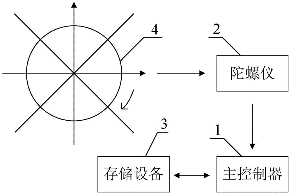
[0017] Specific implementation mode one: combine figure 1 Describe this embodiment, the LED dynamic display device based on persistence of vision described in this embodiment includes a main controller 1, a gyroscope 2 and a storage device 3, the main controller 1 is used to control the LED display screen 4 to display images, The gyroscope 2 is used to monitor the rotation angle of the LED display screen 4 in real time, and the storage device 3 is used to store encoded files and data in the display process;

[0018] The encoded file includes a plurality of data blocks;

[0019] A control module implemented by software is embedded in the main controller 1, and the control module includes the following units:

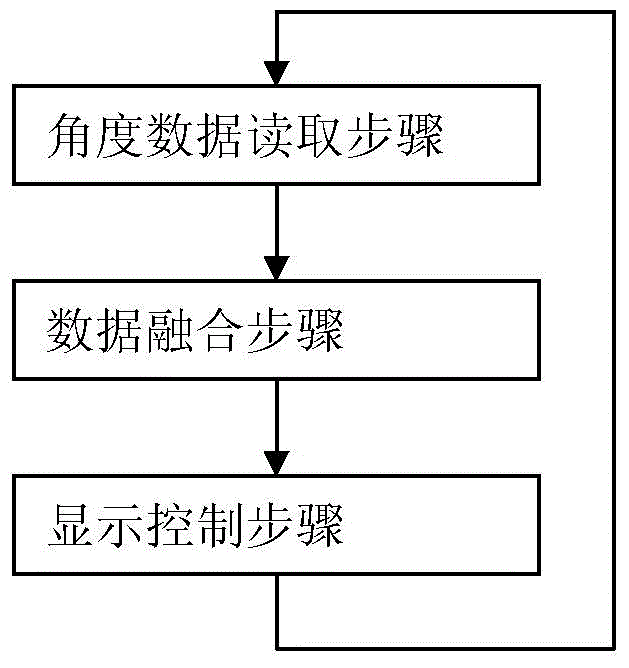
[0020] Angle data reading unit: read the rotation angle θ of the LED display screen 4 measured by the gyroscope 2, and the value range of the rotation angle θ is 0-360°;

[0021] Data fusion unit: calculate the rotation state of the LED display screen 4 according to the...

specific Embodiment approach 2

[0027] Specific Embodiment 2: This embodiment is a further limitation of the LED dynamic display device based on persistence of vision described in Embodiment 1. In this embodiment, the control module further includes a brightness adjustment unit, and the brightness adjustment unit uses The purpose is to control the brightness of the LED display screen 4 according to the current environment information or the brightness data set by the user, the current environment information is obtained by the detector measurement.

[0028] The main controller 1 can adjust the brightness of the LED light bar according to the current environment information and the user's demand, so as to achieve the best display effect.

specific Embodiment approach 3

[0029] Specific Embodiment 3: This embodiment is a further limitation of the LED dynamic display device based on persistence of vision described in Embodiment 1. In this embodiment, the control module further includes an image selection unit, and the image selection unit It is used to select the image to be displayed according to the image data set by the user.

[0030] In this embodiment, the image content to be displayed can be set according to the user's personal preference.


PUM


Abstract

The invention provides an LED dynamic display device and method based on persistence of vision, and relates to LED dynamic display technologies. The LED dynamic display device and method solve the problem that an existing LED dynamic display method cannot display images stably. According to the LED dynamic display device, a storage device is used for storing data of coding files in the display process; a gyroscope is used for monitoring the rotating angle of an LED display screen in real time; a master controller conducts data fusion according to the rotating angle, finds corresponding data blocks in the coding files and then controls the LED display screen to conduct image display. By means of the LED dynamic display device and method, stable images can be displayed, and various target images including dynamic images can still be displayed stably, and even videos can be played under the condition of the variable rotating speeds; meanwhile, the number of LED light bars is not limited, and the device can be used for any rotating LED display platform.

Description

technical field [0001] The invention relates to LED dynamic display technology. Background technique [0002] In recent years, people's enthusiasm for outdoor sports and entertainment has increased and their requirements for equipment have become higher and higher. This poses a great challenge to the vast market for sports and entertainment equipment, and at the same time, it also poses great challenges in technological innovation. Driven by the market, the LED display industry is also undergoing a technological revolution, from traditional static displays to dynamic development, especially adding LED displays to rotating equipment to meet people's demand for dynamic LED displays needs and applications. In the era when LED display screens are widely used, the previous static display screens can no longer attract people's attention. Therefore, installing LED display light bars on rotating objects has become a new starting point. This novel and innovative design will arouse p...

Claims


Application Information

Patent Timeline
Patent Type & Authority Applications(China)
IPC IPC(8): G09G3/32
Inventor 刘兴华
Owner SHENZHEN MAKERSCOPE TECH CO LTD
Why Eureka
Try Eureka