Split cylindrical resonant cavity

A resonant cavity and cylinder technology, which is applied in the field of dielectric property testing of high-frequency printed board substrates, can solve the problem that the test method is not suitable for high-frequency printed substrates

Inactive Publication Date: 2015-04-29
JIANGNAN INST OF COMPUTING TECH
View PDF7 Cites 6 Cited by
  • Summary
  • Abstract
  • Description
  • Claims
  • Application Information

AI Technical Summary

Problems solved by technology

[0004] Although the research on dielectric property test methods has been reported in the literature since the middle of last century, with the continuous increase of test frequency and the continuous development of materials, many test methods are not suitable for high-frequency printed substrates

Method used


Image

  • Split cylindrical resonant cavity
  • Split cylindrical resonant cavity
  • Split cylindrical resonant cavity

Examples


Embodiment Construction

[0020] In order to make the content of the present invention clearer and easier to understand, the content of the present invention will be described in detail below in conjunction with specific embodiments and accompanying drawings.

[0021] figure 1 and figure 2 A split cylinder resonator for measuring the dielectric properties (dielectric parameters) of a high-frequency printed substrate according to a preferred embodiment of the present invention is schematically shown.

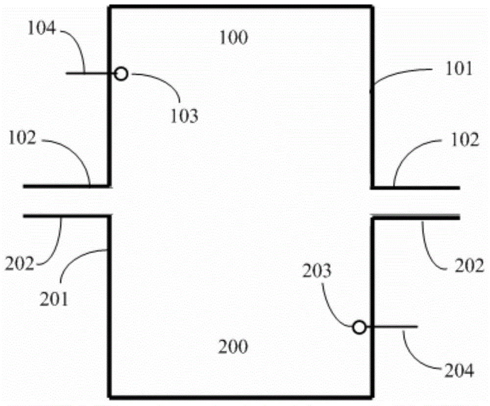
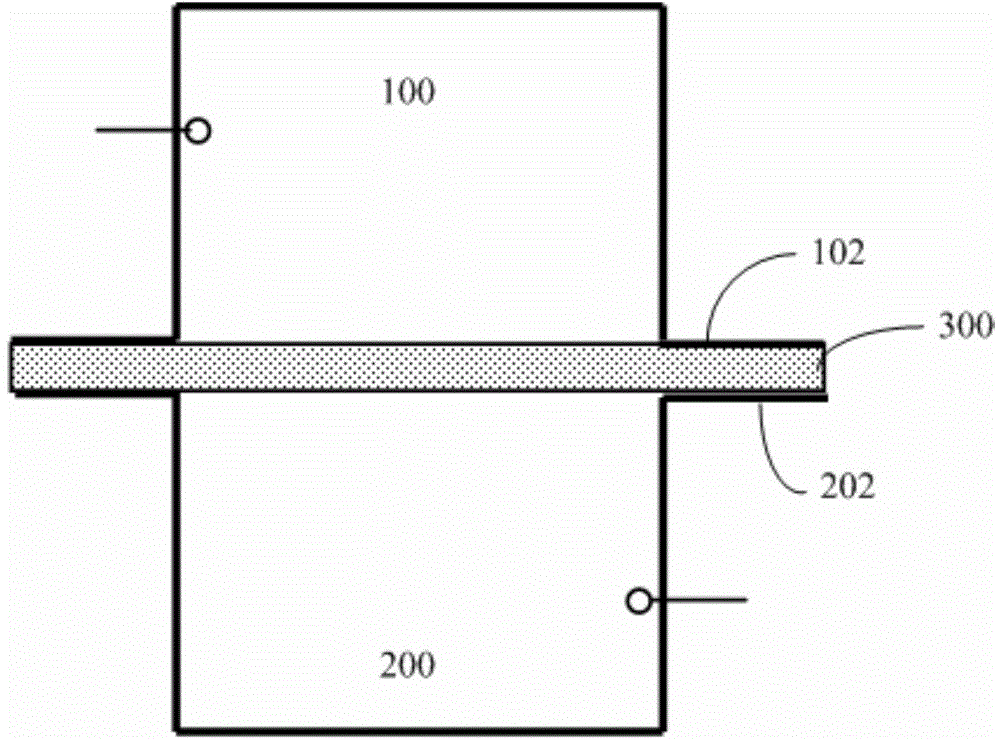
[0022] Such as figure 1 and figure 2 As shown, the split cylindrical resonant cavity according to the preferred embodiment of the present invention includes: an upper cylindrical resonant cavity 100 and a lower cylindrical resonant cavity 200 separated from each other.

[0023] Wherein, the upper cylindrical resonant cavity 100 includes an upper cylindrical cavity 101 with one end closed and one end open, a pair of upper strip conductor flanges 102 arranged on the open end of the upper cylindrical ca...


PUM


Abstract

A split cylindrical resonant cavity comprises an upper cylindrical resonant cavity body and a lower cylindrical resonant cavity body which are separated from each other. The upper cylindrical resonant cavity body comprises an upper-portion cylindrical cavity body with one end closed and one end open, a pair of upper-portion strip-shaped conductor flanges, an upper-portion coupling ring and an upper-portion coaxial transmission line, the upper-portion strip-shaped conductor flanges are arranged on the open end of the upper-portion cylindrical cavity body, the upper-portion coupling ring is arranged inside the upper-portion cylindrical cavity body, the upper-portion coaxial transmission line is connected with the upper coupling ring and penetrates the top wall or the side wall of the upper-portion cylindrical cavity body to connect the upper-portion coupling ring to the outside; the lower cylindrical resonant cavity body comprises a lower-portion cylindrical cavity body with one end closed and one end open, a pair of lower-portion strip-shaped conductor flanges, a lower-portion coupling ring and a lower-portion coaxial transmission line, the lower-portion strip-shaped conductor flanges are arranged on the open end of the lower-portion cylindrical cavity body, the lower-portion coupling ring is arranged inside the lower-portion cylindrical cavity body, the lower-portion coaxial transmission line is connected with the lower coupling ring and penetrates the top wall or the side wall of the lower-portion cylindrical cavity body to connect the lower-portion coupling ring to the outside.

Description

technical field [0001] The invention relates to the field of testing the dielectric properties of high-frequency printed board substrates, more specifically, the invention relates to a split cylinder resonant cavity for measuring the dielectric properties of high-frequency printed substrates. Background technique [0002] Dielectric properties are one of the important performance parameters of high-frequency printed substrates. Accurately testing the dielectric properties of high-frequency printed substrates is crucial to high-frequency circuit design, production, finalization and debugging of high-frequency electronic products For some applications, the test accuracy of the dielectric constant of the printed board is required to be within 2%. [0003] The test accuracy of dielectric properties is related to factors such as frequency, uniformity, anisotropy, temperature, surface roughness, etc. For anisotropic materials, the direction of the test field is crucial. The high-...

Claims


Application Information

Patent Timeline
Patent Type & Authority Applications(China)
IPC IPC(8): H01P7/06G01R27/26
Inventor 贾燕张永华邬宁彪陈文录李小明石小传刘立国贾建中
Owner JIANGNAN INST OF COMPUTING TECH
Why Eureka
Try Eureka