Reactive power and voltage control method for grid-connected inverters of large photovoltaic power station

A voltage control method and photovoltaic power station technology, applied in photovoltaic power generation, AC network voltage adjustment, reactive power compensation, etc., can solve problems such as limited reactive power capacity of photovoltaic inverters, achieve economical operation, and improve voltage stability , The effect of reducing active power loss

Active Publication Date: 2015-04-29
CHONGQING UNIV
View PDF4 Cites 28 Cited by
  • Summary
  • Abstract
  • Description
  • Claims
  • Application Information

AI Technical Summary

Benefits of technology

This technology helps balance the amount of electricity generated by multiple solar panels connected together on one circuit with that used at another location. It improves both efficiency and reliability over existing systems while also optimizes energy use based on factors like weather conditions or other variables such as sunlight intensity levels.

Problems solved by technology

This patents discuss different ways to improve the performance of large photoelectric generations by controlling their own voltages while also considering how they can adjust themselves accordingly. One method involves connecting each generator's feeders directly into the electrical bus without changing its connections. Another approach suggests installing capacitors that store excessive electricity temporarily before being used again after it has been fully charged up due to lack of sufficient charge stored within them. Additionally, some existing solutions involve measuring the voltage levels near the ends of the cables (feeders), allowing for better monitoring and management of these signals.

Method used


Image

  • Reactive power and voltage control method for grid-connected inverters of large photovoltaic power station
  • Reactive power and voltage control method for grid-connected inverters of large photovoltaic power station
  • Reactive power and voltage control method for grid-connected inverters of large photovoltaic power station

Examples


Embodiment Construction

[0027] The preferred embodiments of the present invention will be described in detail below in conjunction with the accompanying drawings; it should be understood that the preferred embodiments are only for illustrating the present invention, rather than limiting the protection scope of the present invention.

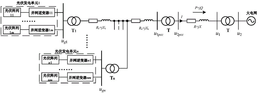
[0028] The schematic diagram of the topology structure of a large-scale photovoltaic power station is as follows: figure 1 shown.

[0029] In the figure, u 1pcc and u 2pcc Respectively represent the voltage of the grid-connected common point of the low-voltage side and the high-voltage side of the distribution station at the sending end. u 1 and u 2 Respectively represent the voltage of the low-voltage side and the high-voltage side of the distribution station at the receiving end. u g1 , u gn Respectively represent the actual grid-connected point voltages of the grid-connected inverters in photovoltaic power generation unit 1 and photovoltaic power generation un...


PUM


Abstract

The invention discloses a reactive power and voltage control method for grid-connected inverters of a large photovoltaic power station. The method comprises steps as follows: a voltage reference unit gives reference voltage uref to a voltage control point; a reactive power setting unit is used for comparing actual voltage of the voltage control point with the reference voltage to obtain voltage deviation, and reactive power reference quantity Qref required by maintaining voltage of the voltage control point is automatically acquired through a PID (proportional-integral-derivative) controller; a reactive power distribution unit automatically performs reactive power distribution between SVG (scalable vector graphics) and each photovoltaic power generation unit; the grid-connected inverters in the photovoltaic power generation units adopts distribution in equal proportion of reactive capacity. According to the method, coordinated control of a reactive power compensation device of the photovoltaic power station and the photovoltaic inverters is sufficiently utilized, grid-connected point voltage fluctuation of the photovoltaic power station is reduced, reactive power support is provided for a power grid, and voltage stability of a weak grid is improved; meanwhile, reactive power is distributed according to line loss of the photovoltaic power generation units, and active loss of the photovoltaic power station is reduced; therefore, the reactive power and voltage control method facilitates safe, economic and stable operation of the large photovoltaic power station accessing the weak grid.

Description


Claims


Application Information

Patent Timeline
Owner CHONGQING UNIV
Why Eureka
Try Eureka