
Reactive power and voltage control method for grid-connected inverters in large-scale photovoltaic power plants

A voltage control method and photovoltaic power station technology, applied in photovoltaic power generation, AC network voltage adjustment, reactive power compensation, etc., can solve problems such as limited reactive power capacity of photovoltaic inverters, achieve economical operation, improve voltage fluctuations, Effect of reducing active power loss

Active Publication Date: 2018-03-02
CHONGQING UNIV
View PDF4 Cites 0 Cited by
  • Summary
  • Abstract
  • Description
  • Claims
  • Application Information

AI Technical Summary

Problems solved by technology

The literature [Reactive power control strategy for low-voltage ride-through of photovoltaic power plants] proposes to use the reactive power output capability of the photovoltaic inverter itself to provide reactive power to the grid, but the reactive power capacity of the photovoltaic inverter is limited in the full state

Method used


Image

  • Reactive power and voltage control method for grid-connected inverters in large-scale photovoltaic power plants
  • Reactive power and voltage control method for grid-connected inverters in large-scale photovoltaic power plants
  • Reactive power and voltage control method for grid-connected inverters in large-scale photovoltaic power plants

Examples


Embodiment Construction

[0028] The preferred embodiments of the present invention will be described in detail below in conjunction with the accompanying drawings; it should be understood that the preferred embodiments are only for illustrating the present invention, rather than limiting the protection scope of the present invention.

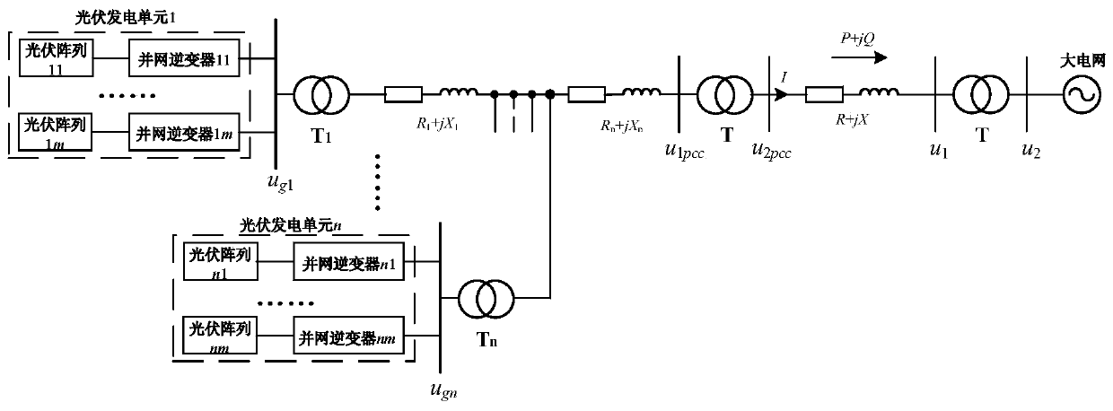
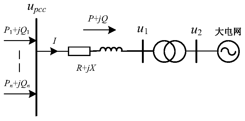
[0029] The schematic diagram of the topology structure of a large-scale photovoltaic power station is as follows: figure 1 shown.

[0030] In the figure, u 1pcc with u 2pcc Respectively represent the voltage of the grid-connected common point of the low-voltage side and the high-voltage side of the distribution station at the sending end. u 1 with u 2 Respectively represent the voltage of the low-voltage side and the high-voltage side of the distribution station at the receiving end. u g1 , u gn Respectively represent photovoltaic power generation unit 1 and photovoltaic power generation unit n The actual grid-connected point voltage of the grid-connected i...


PUM


Abstract

The invention discloses a reactive power and voltage control method for grid-connected inverters of a large photovoltaic power station. The method comprises steps as follows: a voltage reference unit gives reference voltage uref to a voltage control point; a reactive power setting unit is used for comparing actual voltage of the voltage control point with the reference voltage to obtain voltage deviation, and reactive power reference quantity Qref required by maintaining voltage of the voltage control point is automatically acquired through a PID (proportional-integral-derivative) controller; a reactive power distribution unit automatically performs reactive power distribution between SVG (scalable vector graphics) and each photovoltaic power generation unit; the grid-connected inverters in the photovoltaic power generation units adopts distribution in equal proportion of reactive capacity. According to the method, coordinated control of a reactive power compensation device of the photovoltaic power station and the photovoltaic inverters is sufficiently utilized, grid-connected point voltage fluctuation of the photovoltaic power station is reduced, reactive power support is provided for a power grid, and voltage stability of a weak grid is improved; meanwhile, reactive power is distributed according to line loss of the photovoltaic power generation units, and active loss of the photovoltaic power station is reduced; therefore, the reactive power and voltage control method facilitates safe, economic and stable operation of the large photovoltaic power station accessing the weak grid.

Description

technical field [0001] The invention relates to the technical field of photovoltaic power generation, in particular to a method for controlling reactive power and voltage of a grid-connected inverter of a large-scale photovoltaic power station. Background technique [0002] With the continuous reduction of system costs and the continuous improvement of power generation efficiency, building large-scale photovoltaic power plants is an effective way to utilize solar energy on a large scale. Different from small-capacity photovoltaic grid-connected power generation systems, many large-scale photovoltaic power plants are built in desert areas far away from the load center and rich in sunlight resources, and the regional power grids connected to photovoltaic power plants are mostly in remote areas, with scattered loads and long transmission lines in regional power grids. The grid is relatively weak. The light intensity and temperature changes of the photovoltaic power generation ...

Claims


Application Information

Patent Timeline
Patent Type & Authority Patents(China)
IPC IPC(8): H02J3/38H02J3/16
CPCH02J3/16H02J3/383Y02E10/56Y02E40/10Y02E40/30
Inventor 周林杜潇杨明邵念彬郑晨
Owner CHONGQING UNIV
Learn More