Master-slave harmonic reactive compensation generation system and method

A technology for generating system and harmonics, applied in reactive power compensation, reactive power adjustment/elimination/compensation, harmonic reduction devices, etc., which can solve the problem of reducing harmonic reactive power loss, increasing grid active power loss, and deteriorating compensation effect. and other problems to achieve the effect of reducing active power loss, improving compensation efficiency, and reducing input loss

Active Publication Date: 2015-12-16
博格华纳新能源(襄阳)有限公司
View PDF4 Cites 3 Cited by
  • Summary
  • Abstract
  • Description
  • Claims
  • Application Information

AI Technical Summary

Problems solved by technology

[0002] In the current harmonic reactive power compensation generation system, all harmonic reactive power compensation modules are put into use. There is no communication between the modules, and they can only complete their own compensation tasks. There is no systematic overall control scheme, which can still be guaranteed. Harmonic reactive power compensation in the power grid works, but once a harmonic reactive power compensation module in the harmonic reactive power compensation system fails, other modules cannot automatically change their assigned tasks, and the harmonic reactive power loss in the power grid will be unavoidable. to an effective reduction, making the compensation effect worse
[0003] On the contrary, if the reactive power capacity in the system is small, all the harmonic reactive power compensation modules will work as usual, which cannot effectively improve the service life of the modules and also increase the active power loss of the power grid, so the whole system urgently needs a system customized control scheme

Method used


Image

  • Master-slave harmonic reactive compensation generation system and method
  • Master-slave harmonic reactive compensation generation system and method
  • Master-slave harmonic reactive compensation generation system and method

Examples


Embodiment Construction

[0042] It should be noted that, in the case of no conflict, the following technical solutions and technical features can be combined with each other.

[0043] The present invention will be further described below in conjunction with the accompanying drawings.

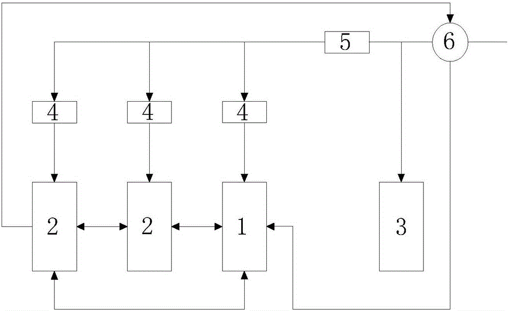
[0044] figure 1 It is a structural schematic diagram of a master-slave harmonic reactive power compensation generation system of the present invention, as figure 1 As shown, a master-slave harmonic reactive power compensation generation system is applied to the harmonic reactive power compensation of the power grid. The system includes:

[0045] The load module 3 is connected to the input terminal;

[0046] At least one secondary harmonic reactive power compensation module 2 is connected to the input terminal respectively, and is used for harmonic reactive power compensation to the power grid;

[0047] The main harmonic reactive power compensation module 1 is connected to the input terminal and each slave harmonic re...


PUM


Abstract

The invention relates to the technical field of harmonic reactive compensation, and especially relates to a master-slave harmonic reactive compensation generation system and method which can be used for carrying out harmonic reactive compensation on a power grid. The system comprises a load module connected with an input end; at least one slave harmonic reactive compensation module connected with the input end and used for carrying out harmonic reactive compensation on the power grid; and a master harmonic reactive compensation module connected with the input end and each slave harmonic reactive compensation module and used for sampling reactive information from the input end, controlling each slave harmonic reactive compensation module and carrying out harmonic reactive compensation on the power grid. According to the invention, the compensation effect is good, and the loss is simultaneously reduced.

Description

technical field [0001] The invention relates to the technical field of reactive power compensation and power quality optimization, in particular to a master-slave harmonic reactive power compensation generating system and method. Background technique [0002] In the current harmonic reactive power compensation generation system, all harmonic reactive power compensation modules are put into use. There is no communication between the modules, and they can only complete their own compensation tasks. There is no systematic overall control scheme, which can still be guaranteed. Harmonic reactive power compensation in the power grid works, but once a harmonic reactive power compensation module in the harmonic reactive power compensation system fails, other modules cannot automatically change their assigned tasks, and the harmonic reactive power loss in the power grid will be unavoidable. to an effective reduction, making the compensation effect worse. [0003] On the contrary, if...

Claims


Application Information

Patent Timeline
Patent Type & Authority Applications(China)
IPC IPC(8): H02J3/18H02J3/01
CPCY02E40/30Y02E40/40
Inventor 李成杰彭华良
Owner 博格华纳新能源(襄阳)有限公司
Why Eureka
Try Eureka