
Method capable of performing centralized monitoring on whole grid reactive power voltage state(s) by adopting automatic voltage control system

A control system and automatic voltage technology, applied in reactive power compensation, AC network voltage adjustment, reactive power adjustment/elimination/compensation, etc., can solve the problem that the control strategy does not adapt to the operating conditions, exceeds the adjustment ability of the control system, and has many operating data Problems such as over-limits, to reduce line reactive power transmission, improve control level, and ensure qualified results

Active Publication Date: 2019-02-15
SHANGHAI MUNICIPAL ELECTRIC POWER CO
View PDF0 Cites 3 Cited by
  • Summary
  • Abstract
  • Description
  • Claims
  • Application Information

AI Technical Summary

Problems solved by technology

[0010] 2. Under normal working conditions, the operating data exceeds the limit many times: there are two main reasons for the operating data exceeding the limit. One is that the operating condition exceeds the adjustment ability of the control system, and the other is that the control strategy does not adapt to the specific operating conditions.

Method used


Image

  • Method capable of performing centralized monitoring on whole grid reactive power voltage state(s) by adopting automatic voltage control system
  • Method capable of performing centralized monitoring on whole grid reactive power voltage state(s) by adopting automatic voltage control system
  • Method capable of performing centralized monitoring on whole grid reactive power voltage state(s) by adopting automatic voltage control system

Examples


Embodiment Construction

[0031] The present invention will be further described below in conjunction with the accompanying drawings.

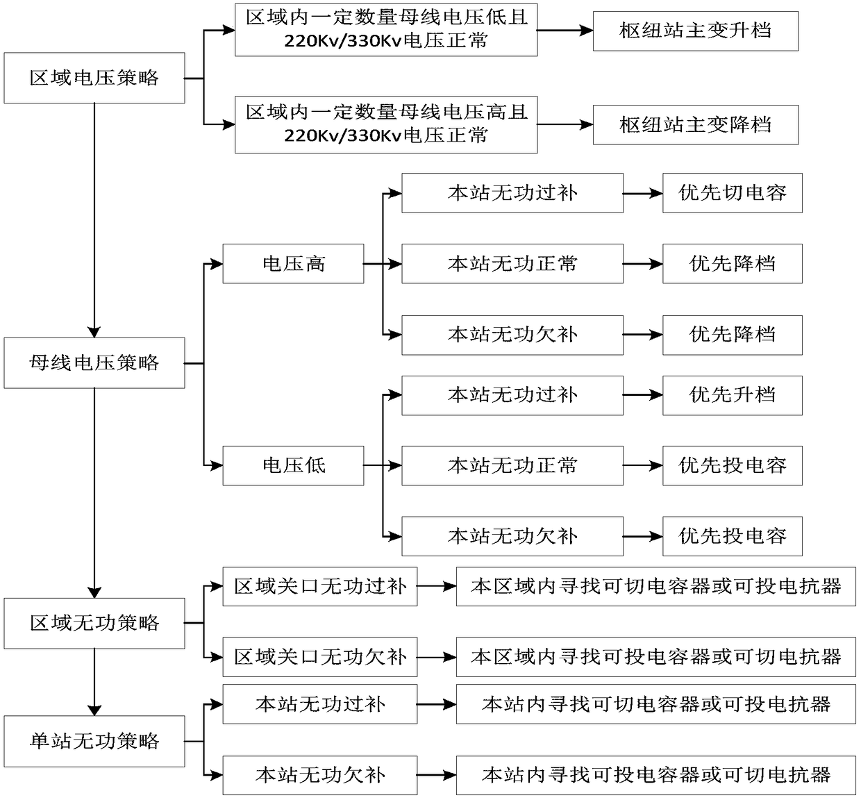
[0032] The technical solution of the present invention provides a method for centralized monitoring of the reactive power and voltage state of the whole network by using an automatic voltage control system. The invention lies in:

[0033] 1. Strengthen centralized monitoring and make abnormal records

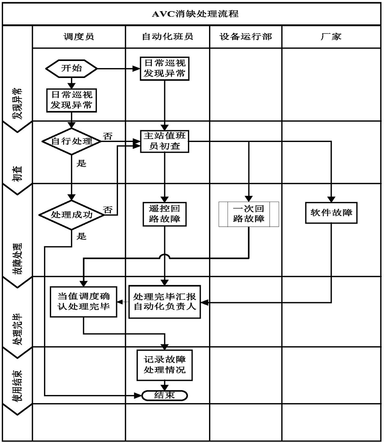
[0034] Strengthen the monitoring and recording of the problems that arise in the operation of the AVC system, and require each dispatcher to timely reset the alarm lockout signal of the AVC system and record the station, time, lockout information, processing method and closed-loop situation of the alarm lockout corresponding records. The out-of-limit information found during operation should also be dealt with in a timely manner, and corresponding records should be made. When the shift is handed over, each dispatcher must include the AVC operation status of the day in ...


PUM


Abstract

The present invention discloses a method capable of performing centralized monitoring on whole grid reactive power voltage state(s) by adopting an automatic voltage control system, pertaining to the field of scheduling, management and controlling of a power grid. According to the method, alarm locking signal(s) of an AVC system and over-limit information found in operation are included into a closed-loop processing system, centralized and outstanding problem(s) are analyzed, abnormality causes and solutions are found, abnormality handling processes are constantly improved, and detailed and complete treatment processes are worked out. The method can improve the operation performance of the AVC system, further improve the control level of voltage reactive power, ensure the safe and stable operation of the power grid, guarantee the qualification of voltage(s) and power factor(s) of related node(s), minimize line reactive power transmission to the greatest extent and reduce the active power loss caused by unnecessary reactive power flow(s) in the power grid. The method can be widely used in the field of the scheduling, the management and the controlling of the power grid.

Description

technical field [0001] The invention belongs to the field of power grid dispatching management and control, and in particular relates to a method for centralized monitoring of the reactive voltage state of the whole network by using an automatic voltage control system. Background technique [0002] The automatic voltage control system of the power grid (Automatic Voltage Control, referred to as AVC) realizes the optimal control of voltage and reactive power compensation equipment through online analysis and calculation of data such as telemetry and signal of each node in the power system, so that the voltage pass rate, reactive power The control quantities such as power transmission and power factor meet the boundary conditions, improve the operation of the power system, reduce line losses, and improve the stability and economy of the power system. [0003] The main function of the grid automatic voltage control system (AVC) is to ensure that the voltage and gate power facto...

Claims


Application Information

Patent Timeline
Patent Type & Authority Applications(China)
IPC IPC(8): H02J3/16H02J3/18
CPCH02J3/16H02J3/18Y02E40/30
Inventor 孙歌沈凌徐焰姚璟杰陈志亮高凯赵彬刘俊陈辰孙迪
Owner SHANGHAI MUNICIPAL ELECTRIC POWER CO
Learn More