Material self-unloading device

A self-unloading device and material technology, applied in the field of machinery, can solve the problems of increasing machinery use costs and labor costs, wasting energy, unfavorable production efficiency, etc., and achieve the effects of saving energy, improving efficiency, and saving time

Active Publication Date: 2015-05-06
SOUTH CHINA AGRI UNIV
View PDF5 Cites 4 Cited by
  • Summary
  • Abstract
  • Description
  • Claims
  • Application Information

AI Technical Summary

Problems solved by technology

However, in logistics machinery, agricultural harvesting machinery and other industries, due to the use of power sources such as hydraulic drive and motor drive, during the continuous unloading process of materials, it will increase the cost of machinery use and labor costs, waste energy, and is not conducive to improving production efficiency

Method used


Image

  • Material self-unloading device
  • Material self-unloading device
  • Material self-unloading device

Examples


Embodiment 1

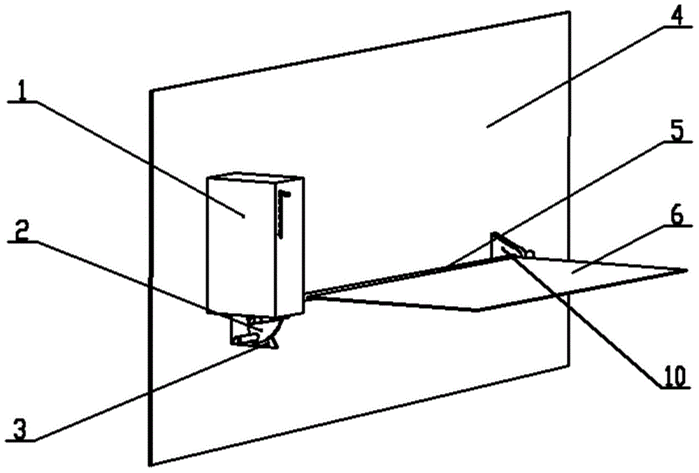
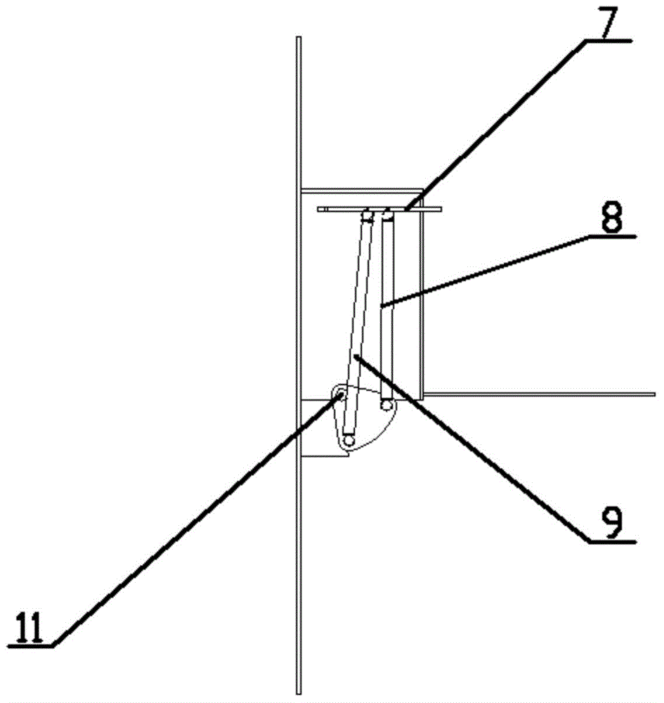
[0029] like figure 1 and figure 2 As shown, a material self-unloading device that swings through the elasticity and gravity of the tension spring includes a fixed plate 4, a rotating shaft 5, a material plate 6, a first tension spring 8, a second tension spring 9 and a spring connection Plate 2, wherein one end of the material plate 6 is fixedly connected to the rotating shaft 5, the upper surface of the material plate 6 is set as a rough surface, and the purpose of setting the upper surface of the material plate 6 as a rough surface is to ensure that the material plate 6 and the material are tilted and in a critical position. At this point, the material will not slide down so that it cannot break through the critical point. Specifically, the critical angle of the material plate is determined by the friction coefficient between the material and the material plate, and the critical angle should be smaller than the self-locking angle between the material and the material plate...

Embodiment 2

[0032] This embodiment is the same as Embodiment 1 except for the following features.

[0033] The spring connecting plate 2 is arranged on the rotating shaft 5, and can also be arranged on the right side of the rotating shaft 5 according to the installation situation of the material self-unloading device. The spring connecting plate 2 is arranged in a circular shape. One end of the material plate 6 is fixedly connected to the rotating shaft 5, and the upper surface of the material plate 6 is a granular rough surface.

Embodiment 3

[0035] This embodiment is the same as Embodiment 1 except for the following features.

[0036] The spring connecting plate 2 is arranged on the rotating shaft 5, and can also be arranged in the middle of the rotating shaft 5 according to the installation situation of the material self-unloading device. The spring connecting plate 2 is arranged in a square shape. One end of the material plate 6 is fixedly connected to the rotating shaft 5, and the upper surface of the material plate 6 is a striped rough surface.


PUM


Abstract

The invention discloses a material self-unloading device. The material self-unloading device is characterized by comprising a fixing board, a rotary shaft, a material board, a first extension spring, a second extension spring and a spring connection board, wherein the material board is fixedly connected with the rotary shaft; the rotary shaft is connected with the fixing board through a rotary connection structure; the top ends of the first extension spring and the second extension spring are hinged to the fixing board; the bottom ends of the first extension spring and the second extension spring are hinged to the spring connection board; the spring connection board and the material board are fixedly connected through the rotary shaft. By arrangement of a mechanical device, materials are unloaded in a swinging mode through action of gravity and elasticity to solve the problem that an additional power source is needed in the material unloading process, unloading of the materials is accelerated and the recycling work of the material board is rapidly finished by utilization of the characteristic of the extension springs, and therefore a large number of energy sources and a large amount of time are saved, and the production efficiency is improved.

Description

technical field [0001] The invention relates to the technical field of machinery, in particular to a material self-unloading device. Background technique [0002] In logistics machinery, agricultural harvesting machinery and other industries, material unloading is often achieved by lifting the material to a certain height through a power source such as hydraulic drive or motor drive, or tilting the material and using the unbalanced force on the material to achieve the purpose of material unloading. However, in logistics machinery, agricultural harvesting machinery and other industries, due to the use of power sources such as hydraulic drive and motor drive, during the continuous unloading process of materials, it will increase the cost of machinery use and labor costs, waste energy, and is not conducive to improving production efficiency. Contents of the invention [0003] The purpose of the present invention is to overcome the shortcomings and deficiencies of the prior ar...

Claims


Application Information

Patent Timeline
Patent Type & Authority Applications(China)
IPC IPC(8): B65G65/00B65G47/74
CPCB65G47/74
Inventor 杨丹彤何霖黄峥李福强陈舒凯吴俊宇
Owner SOUTH CHINA AGRI UNIV
Why Eureka
Try Eureka